# Tilia Griffin - How To Generate And Offset A Cut Path
Griffin has the ability to generate cut paths for artwork and images that do not contain cutting information. This step-by-step guide will walk you through this process.
# Step-by-step guide
# Step 1 - Import Artwork
Begin by creating a new job and bringing artwork into the Griffin art board. There are three ways to import artwork: Navigate to the menu bar and select File > Import Artwork Click the "" button in the top left corner of the Griffin application Simply drag files from your finder into the artboard
# Step 2 - Check for Existing Cut Information
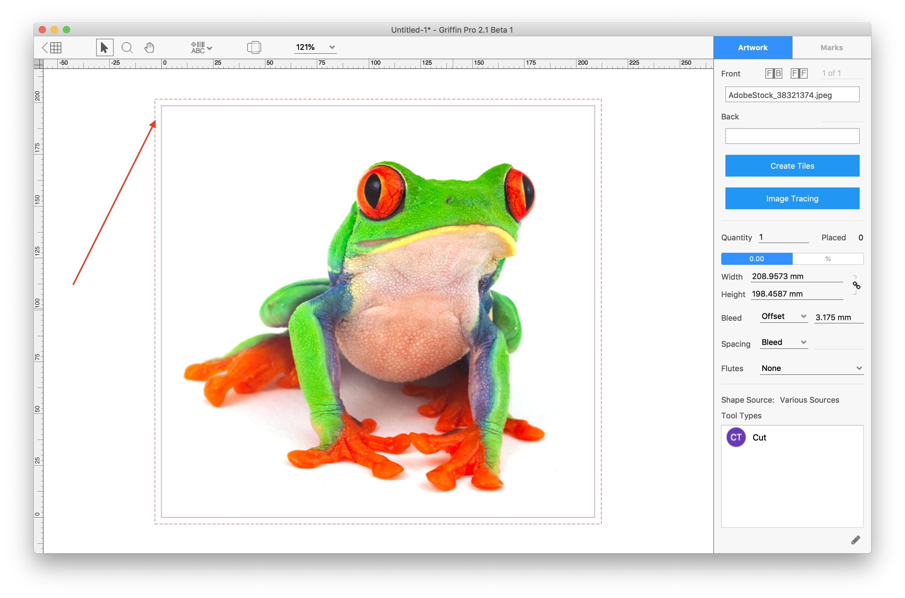
Next, check if the file already contains a spot color or layer that is mapping to a cut line. Do this by double clicking the one-up artwork within the Griffin art board to bring you into the one-up view.
- If the purple cut line and dotted red bleed line match the contours of the desired cut path then the file contains a cut path.
- If the purple cut line and dotted red bleed line are rectangular then Griffin is mapping the cut line to the artwork trim box.
In this second case, let's generate a new cut path for the artwork.
note
If a spot color or layer for cutting exists in the file and Griffin is not finding it, please refer to our tutorial on how to map Tool Types in Griffin.
# Step 3 - Image Trace
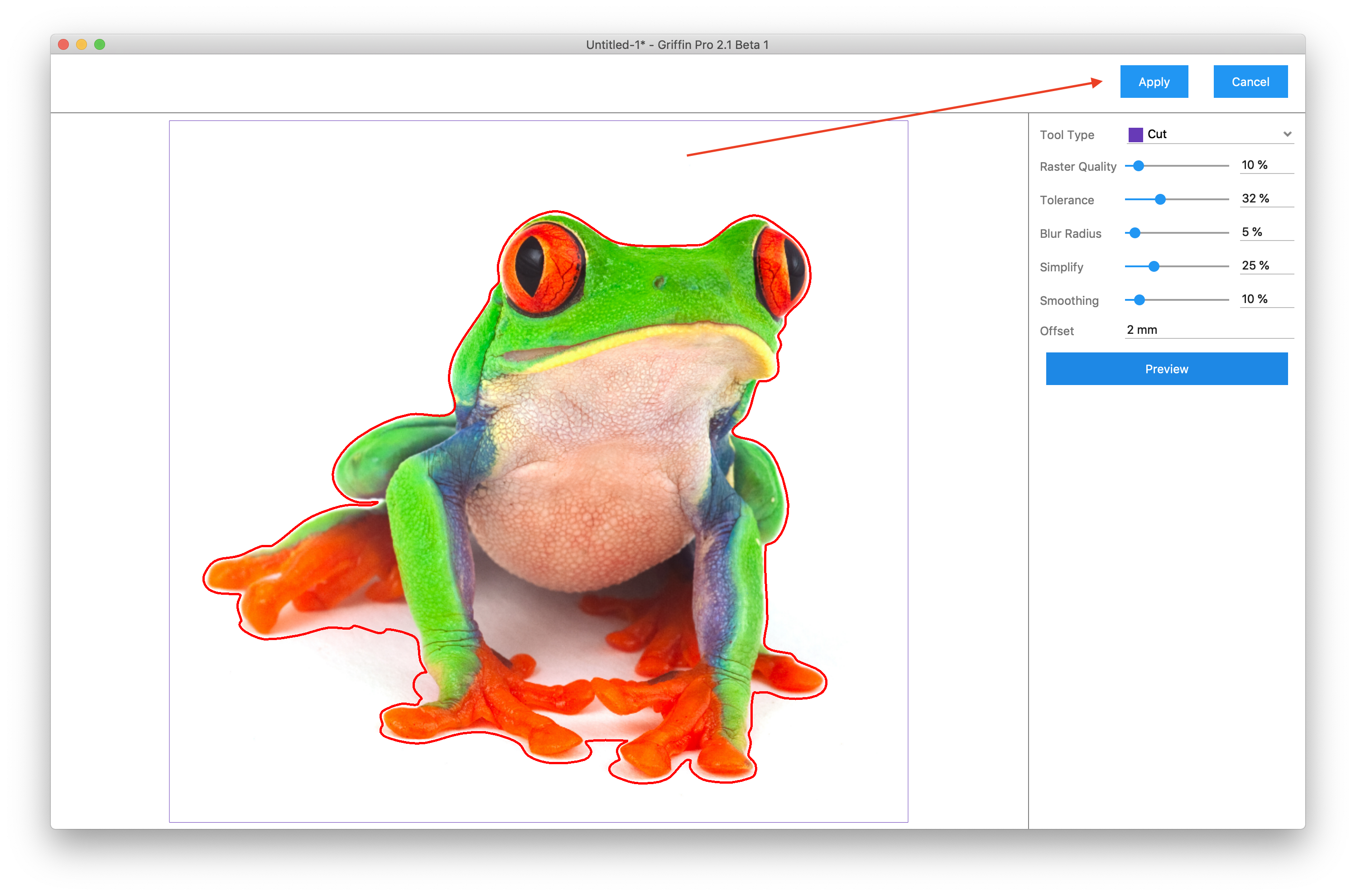
Click the "Image Tracing" button in the left side toolbar. This will open the cut path generation interface. You will see the following options listed from top to bottom:
- Tool Type – Cutting tool type to use for the generated cut tool path.
- Raster Quality – Quality of the raster image to use for generating the cut tool path. A value of 100% will rasterize the image at full size up to a limit of 10 megapixels. Lower values will scale the image down for faster processing and in some case preferred results as less detail is used for tracing.
- Tolerance – Amount of color difference to allow before adjacent colors are considered different. A value of 0% means no tolerance in color differences is allowed while 100% is the maximum allowed tolerance in color differences.
- Blur Radius – The amount of blurring to apply to edges that are encountered during edge detection. A higher blur radius means more blurring is applied during edge detection which can lead to less jagged paths.
- Simplify – The amount of simplification to apply to the generated path. Simplify works by removing points on the path that are within a certain tolerance. A value of 0% disables path simplification while a value of 100% will use the highest allowed tolerance when removing points.
- Smoothing – Smoothing converts individual points on the generated path to Bezier curves to produce smoother paths. A value of 0% disables path smoothing while a value of 100% will perform the most aggressive path curve smoothing.
- Offset – Additional offset distance to expand the generated path.
- Preview – Updates the generated path preview with the current settings. Once you have found the right settings for the given artwork, click the “Apply” button in the upper-right corner to apply the new shape path to the artwork.
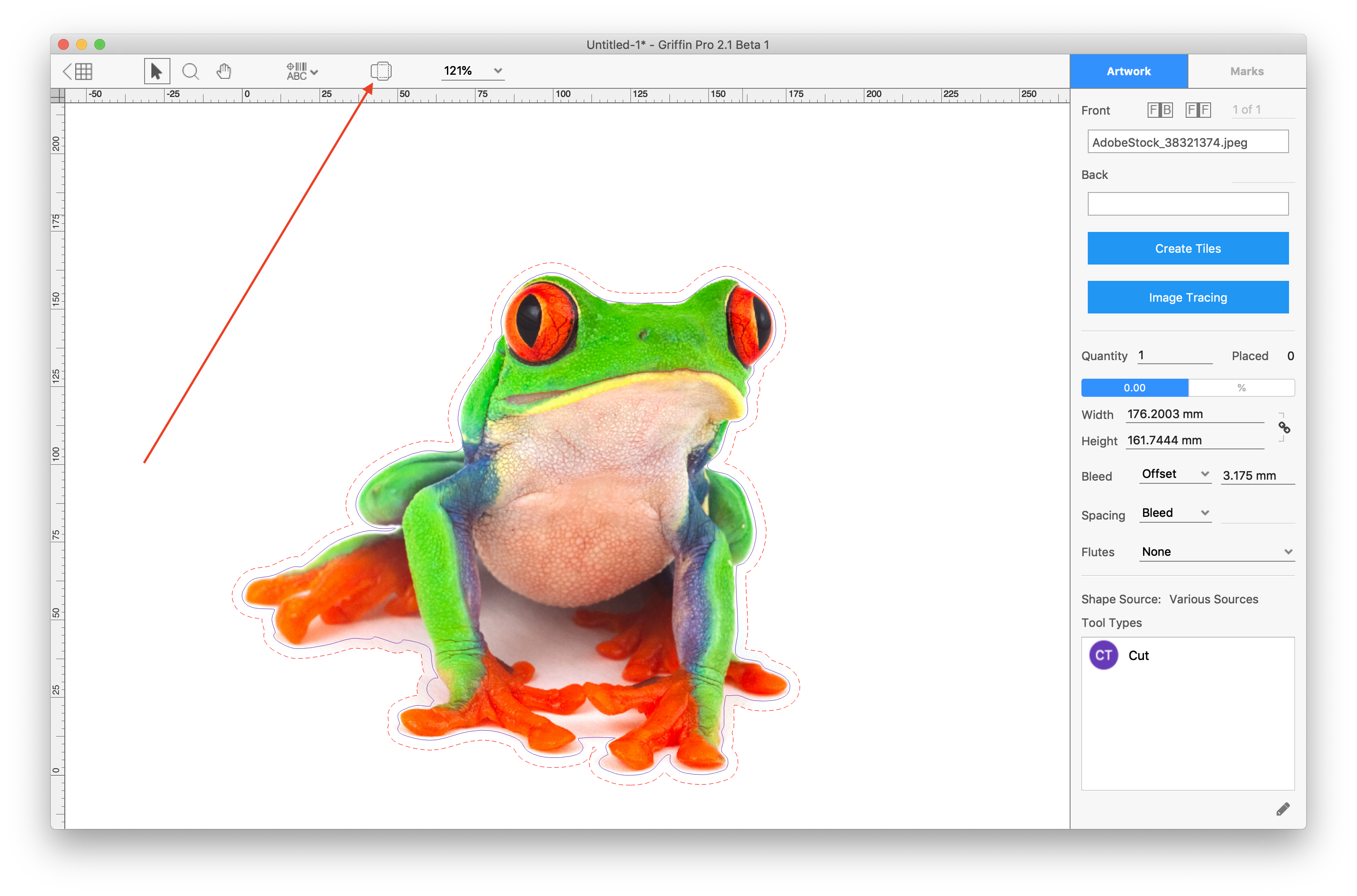
# Step 4 - Refine your new cut path
Now that you have generated a cut path, you may want to fine tune the results. In the one-up view, select the " " icon in the top of the art board to edit the tool path.
You are now in Tool Path Edit mode where you can directly manipulate the artwork tool paths by using the tools from the Toolbar:
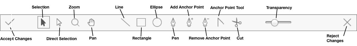
- Accept Changes – Commit the changes that were made during this editing session.
- Selection Tool – Select tool paths in the Main View.
- Direct Selection Tool – Select and move individual control points on a path.
- Zoom Tool – Zoom in and out of the Main View.
- Hand Tool – Grab the Main View to move around and scroll to zoom in and out.
- Line Tool – Draw lines directly into the Main View.
- Rectangle Tool – Draw rectangles directly into the Main View.
- Ellipse Tool – Draw ellipses directly into the Main View.
- Pen Tool – Draw paths (lines and curves) directly in the Main View.
- Add/Remove Anchor Point Tools – Add or remove anchor points from an existing path.
- Anchor Point Tool - Select anchor points and manipulate the handles to change the curve shape.
- Cut Tool – Split a path segment.
- Reject Changes – Exit out of Tool Path Edit mode without applying any changes made in the edit session.
In Tool Path Edit mode you can also change the tool type for any tool path by selecting the path(s) and choosing a different ‘Tool Type’ in the Sidebar.
# Step 5 - Accept Changes
Once you are satisfied with the edits you have made, click the "" button to accept changes.