# Products
# Overview
Products are the fundamental unit in Phoenix. Below, we go in depth into the various types of products in Phoenix, how to create products, setting properties, and importing products from a CSV file.
# Types of Products
Phoenix understands that different products serve different purposes for various market segments, and as such have different properties based on how they are produced. The product types are:
| Flat | Bound | Folded | Tiled |
|---|---|---|---|
 |  |  |  |
# Flat
A 'Flat' product type (flatwork) in Phoenix is any non-bound, non-folded product or a product that only contains packaging folds. A 'Flat' product can consist of one or two pages (front only or front & back).
Examples include (but not limited to): business cards, postcards, leaflets, flyers, posters, folding carton, corrugated, banners, labels, shrink-sleeves, etc...
# Bound
A 'Bound' product type in Phoenix is any product which will contain many pages that are printed using mulitple printed signatures (sheets) which are gathered and bound together to create a finished booklet.
# Folded
A 'Folded' product type in Phoenix is any product which will contain many pages that are printed using one printed signature (sheet) which is folded to create the finished booklet.
Examples include (but not limited to): folded flyers, brochures, 4-page single fold or half fold, tri-fold or letter fold, z-fold, gate folds, etc...
# Tiled
A 'Tiled' product type in Phoenix is any product which will require tiling of the graphical element. Tiling is common for large-format or wide-format graphics where the finished product exceeds the size of the printer and/or cutting equipment. A 'Tiled' product in Phoenix makes the printing process easier by ensuring your overlaps/gaps/bleeds will be correct, plus there’s no need to create a separate file per tile as there is when you use Photoshop or Illustrator.
# Creating Products
Products can be created in multiple ways:
- Defining die dimensions (New Empty Product)
- From PDF or AI artwork
- From CAD file
- From the Die Design Library
- From CSV file
- By dragging and dropping artwork files into Phoenix
- Automatically, using a hot folder, 3rd party integration, or via the Phoenix API
# New Empty Product
Products can be created by simply defining the width and height. This is referred to as an Empty Product, with no artwork specified. This is particularly useful for creating layouts with placeholder shapes before you have the artwork, or to create a reusable layout template where artwork can be replaced at any time.
To create an empty product, go to the File menu, find the product type for which you want an empty product, and then select the corresponding "Empty…" option.
Alternatively, select one of the "New ... Product" options from the Product Panel action menu (upper left corner of panel) and then choose "Empty"
When selected, the New Empty Product dialog will appear, where the dimensions and select properties of the product are defined
| Field | Description |
|---|---|
| Name | Unique name of this product. |
| Quantity | Order Quantity needing to be fulfilled for this product. |
| Due Date | (Optional) The date the product is due. |
| Stock | Stock this product is to be printed on. |
| Grain | Grain direction required for this product: Horizontal, Vertical or None. Grain direction and current sheet grain are used to determine product orientation the ganging tools. |
| Width | Width of product die. |
| Height | Height of product die. |
| Bleed | Bleed offset from rectangular die defined by Width and Height. |
When you are done click the OK button. You can assign artwork, changed the bleed, change the die line and more in Product View. You can also edit properties by selecting the product in the Product Panel and editing the properties in the Properties Panel.
# New Product from Artwork
Products can be created directly from PDF and AI artwork files, as well as from image files. Products can be created from a "New Product" dialog in the File menu or the Products panel. In addition, flat products can be created by dragging and dropping into the file into a layout. By default, for PDF files the PDF Trim Box is used to create a rectangular die line of the new product and the first page is assigned as the front side artwork of the new product.
In Preferences -> Product you can change the default behavior to automatically set die design from Line Type mappings. After creating the product, you can set the die line to spot colors in the artwork by going into Product View and selecting the cut and optionally crease line spot colors.
For image-base file types such as TIFF, PNG, BMP, JPG, and GIF, the dimensions of the image are used to create a rectangular die line for the new product. If the artwork file contains exactly two pages, the second page artwork is automatically assigned to the back side of the product. This default behavior can also be changed in Preferences -> Product by editing the Page Handling options.
# Using New Product from Artwork Dialog
To create a new product from artwork using the New Product from Artwork Dialog, go to the File menu, find the "New ... Product" flyout menu for the product type you are wanting to create, and then click the corresponding "From Artwork..." button.
Alternatively, select "New ... Product" for the desired product type from the Product Panel action menu and then click "From Artwork..." (upper left corner of panel).
Once selected a file dialog will appear. Select the artwork file you wish to import and click OK. Once the artwork has been loaded you will be presented with a dialog allowing you to define select product properties.
| Field | Description |
|---|---|
| Name | Unique name of this product. |
| Quantity | Order Quantity amount needing to be fulfilled for this product. |
| Due Date | (Optional) The date the product is due. |
| Stock | Stock this product is to be printed on. |
| Grain | Grain direction required for this product: Horizontal, Vertical or None. Grain direction and current sheet grain are used to determine product orientation the ganging tools. |
| Width | Width of product die. |
| Height | Height of product die. |
| Bleed | Bleed offset from rectangular die defined by Width and Height. |
# Using File Drag-and-Drop
Products can also be created from artwork by dragging the artwork into Phoenix from the desktop or file explorer. The overall behavior is the same as creating product from dialog with ordered amount and grain direction set to default values from the Products section in Preferences (Edit menu). Product name will be generated from the file name of the dropped in artwork file.
Pressing Alt / Option key during artwork drop will cause Phoenix to look through the existing list of line type mappings in preferences to automatically create the product die design based on spot inks and PDF layer paths in the artwork.
# New Product from CAD
Module: CAD Products can be created from CAD files. Phoenix supports CFF2, DDES2, DDES3 and DXF CAD formats. Select a 1-up design within a CAD file using the New Product from CAD dialog or drag- and-drop a CAD file into Phoenix to automatically create products for each unique 1-up in the CAD file. If a CAD file contains lines mapped to bleed, a bleed mask will be created from the CAD bleed lines, otherwise a bleed is generated as an offset from the CAD cut lines using the Default Bleed defined in the project.
Using New Product from CAD Dialog To create a new product from artwork using the New Product from CAD Dialog, go to the File menu and select "New Product from CAD".
Alternatively, select "New Product from Artwork…" from the Product Panel action menu (upper left corner of panel).
Once selected a file dialog will appear. Select the CAD file you wish to import and click OK. Once the CAD file has been loaded you will be presented with a dialog allowing you to choose the 1-up design you want to use as well as CAD line mappings and product properties.
| Field | Description |
|---|---|
| Die | Name of 1-up die within CAD file to use to create new product. |
| Name | Unique name of this product. |
| Quantity | Order Quantity amount needing to be fulfilled for this product. |
| Due Date | (Optional) The date the product is due. |
| Stock | Stock this product is to be printed on. |
| Grain | Grain direction required for this product: Horizontal, Vertical or None. Grain direction and current sheet grain are used to determine product orientation the ganging tools. |
| Preset | CAD Import preset to use to define line mappings such as cut, crease and bleed. For well- defined CAD formats like CFF2 and DDES, most often the default presets will correctly map line types. CAD files from certain applications and the DXF format in general can contain non-standard line types that need user-defined mappings to correctly import the 1-up design. User defined presets are a simple, powerful way to define the line mappings from a specific client or application to reuse again in the future. |
| Line Mappings | Table of line type mappings used to map lines to cut, crease and bleed lines in the product. Line mappings can be added, removed or edited with the icons below the line mappings table. Line mappings can also be defined directly in the interactive preview pane on the left by right clicking on a line and selecting the appropriate line type from the context menu. |
| Save Preset | To save the current line mappings as a preset to reuse again in the future either here or in the Die Import Wizard, click this button and enter the name you would like to save the preset as. If using an existing preset name, you will be prompted to confirm you would like to override the existing preset. |
# New Product from Die Design
Choose a 1-up die design that has already been imported into the Die Design Library to create a product from.
Using the New Product from Die Design Dialog
To create a new product from Die Design using the New Product from Die Design Dialog, go to the File menu and select "New Product from Die Design".
Alternatively, select "New Product from Die Design…" from the Product Panel action menu (upper left corner of panel).
In the Dialog, Select the die design you want to use and specify the properties.
| Field | Description |
|---|---|
| Name | Unique name of this product. By default, die design name is populated in this field. |
| Quantity | Order Quantity amount needing to be fulfilled for this product. |
| Due Date | (Optional) The date the product is due. |
| Stock | Stock this product is to be printed on. |
| Grain | Grain direction required for this product: Horizontal, Vertical or None. Grain direction and current sheet grain are used to determine product orientation the ganging tools. |
# Autosnap
Autosnapping artwork into a product die or die template is one of the most powerful features in Phoenix. Autosnap handles a wide range of scenarios such as mismatched rotation, non-centered artwork, incorrect Trim Box sizes, etc., providing perfect placement of artwork in the product die for a vast majority of cases.
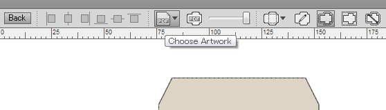
The normal way to autosnap artwork into a die is by clicking on the Choose Artwork button in the Product View or Layout View toolbar.
A shortcut for snapping artwork into the die is to hold down the Control key while dragging and dropping the artwork file into the desired side (Front or Back) in Product View or in Layout View. If Control key is not held down, a new product will be created from the artwork.
When in Layout View, the artwork being dropped into Phoenix will be snapped into all selected product or die template items in the Artboard. If all instances of a product are selected, artwork will be snapped into the existing product. In cases where a subset of all product's instances are selected, the following steps take place automatically:
- A new product will be created using the name of the artwork file by duplicating the existing product.
- The artwork will be autosnapped into this new product.
- Selected product or template items in the Artboard will be replaced by instances of this new product.
If you are drilled into the context of a product instance in Layout View, you are editing the product itself and behavior is the same as in Product View.
Also note, if you are snapping to the Front of the product or template item and the given artwork has two pages, the first page automatically snaps into the Front of the product while the second page snaps to the Back of the same product. If you need to snap different pages of the artwork file to the given side(s) of a product, click on the Choose Artwork button down arrow to open the Page Mapping dialog.
# General Properties
# Bleed
To change the bleed settings for individual product (or multiple products at one time):
- Click to select the Product (or Products) you wish to modify
- Look to the right side of the window to find the Product Properties sidebar
- Scroll down to find the Bleed Type setting. This allows you to choose how you want bleed in this product
- None - no bleed will be allowed for the selected product(s)
- Contour - bleed will be specified as a distance from the contour
- Margins - bleed will be specified as a distance from each side of the product. This should only be used with rectangular products.
- Adjust the Bleed Type option to your preferred setting
- Click on the existing values to modify the bleed values, then click away or press Enter/Return to accept the setting.
# Other Properties
| Property | Description |
|---|---|
| Type | Type of product |
| Name | Unique name of the product |
| Color | Color to use to represent the product in Phoenix. This color is not printed, but only a representation within the UI to identify the product, and will also be displayed in an exported project report |
| Index | Index of the product within the project |
| Description | Optional product description |
| Notes | Optional notes to associate with product |
| Quantity | Number of product ordered in the project, also referred to as ordered quantity |
| Due Date | Product due date |
| Group | Optional product group used in Imposition AI |
| Priority | Optional priority of product starting from 1 as highest priority |
| Min Overruns | Minimum overrun percentage allowed for the product |
| Max Overruns | Maximum overrun percentage allowed for the product |
| Bundle-size | Bundle size needed for product. When set, Imposition AI tools will ensure layouts including this product will have run length multiples of this bundle size |
| Placed | The number of products placed on a layout |
| Total | The total number of products produced when the project is run the specified number of times in the project run length |
| Overrun | The number of overruns of the product |
| Overrun % | The overrun percentage, calculated as total / quantity |
| Stock | Stock of product |
| Grain Direction | Grain direction of product ('Horizontal', 'Vertical', 'Consistent', 'None') |
| Processes | List of processes the product will route through which controls process-specific behavior. For example 'Printing, Cutting' |
| Mode | When clicking on 'Process Setting', Mode is the name of Mode to run the given process at |
| Mode Value | When clicking on 'Process Setting', Mode Value is the specific mode value to run the given process at |
| Rotation | Rotation type to allow in product, defaults to Product Settings defaults unless allowed-rotations is defined in which case 'Custom' rotation type is assumed = ['Any', 'Orthogonal', 'None', 'Custom'] |
| Allowed-rotations | Allowed rotations of product when rotation type is 'Custom' |
| Templates | List of templates this product can be used with |
| Component Type | Type of product component: flat, tiled, bound, folded For example, a 32 page bound product with an F16-7 folding pattern will be made up of two bound components (2x F16-7 signatures) |
| Part | Product parts that make up this product |
| Width | Width of product when creating a custom size product or the desired scaled width or scale percentage when creating the product die from a die design or artwork |
| Height | Height of product when creating a custom size product or the desired scaled height or scale percentage when creating the product die from a die design or artwork |
| Double-sided | If product is two-sided (Boolean) |
| Bleed-type | Product bleed type = [Margins, Contour, Cad, or None] = ['Margins', 'Contour', 'CAD', 'None'] |
| Bleed Margin | Scalar offset from die design to generate bleed |
| Bleed Margins | Four sided bleed margins when bleed type is Margins |
| Spacing Type | How products should be spaced. Choose from Margins, Uniform Spacing, Spacing from Bleed, or Spacing from Tool |
| Spacing Margin | Single scalar spacing offset when spacing type is Uniform |
| Spacing Margins | Four sided spacing margins when spacing type is Margins |
| Offcut Margins | Four sided offcut margins |
| Die Type | Die design type Allowed: Rectangle, Irregular, Open |
| Die Name | Name or 1-up die |
| Die Source | Name of the source file for the dieline |
| Die Path | Local path to the die source file |
# Product Inks
Phoenix will automatically find the inks in a product and display them in the Inks panel. Inks are a fundamental part of how Phoenix works, so let's take a closer look at how this all works.
# Ink Mappings
First, there are different types of inks, such as Normal inks (process or spot color printing inks), Coatings, Technical, and so on. The ink types are set based on the Ink Mappings in the Phoenix Preferences. You can also set the ink type manually by right-clicking on the ink type in the Inks panel. Phoenix will use this ink type to determine what presses and devices are capable of producing the product when using Imposition AI.
# Tool Type Mappings
In addition to Ink Mappings, Phoenix uses Tool Type Mappings. Tool Types represent any tooling to be done on a product, such as die cutting, creasing, or scoring. You can learn more about Tool Types and how they are configured on the Tool Type Mappings page.
# Automatic Ink Coverage Calculation
Phoenix 8.0 also introduces Automatic Ink Coverage Calculation. Phoenix auto-computes ink coverage percentages in product artwork by rasterizing each separation of the artwork and analyzing the raster data. This new feature is controlled via the new Color Analysis property in each product page. By default, Color Analysis is set to Fast which analyzes the artwork content stream without rasterizing in the same way as previous versions of Phoenix. When Color Analysis is set to Raster, the new separations raster algorithm automatically computes ink coverages in that page’s colors list and removes any colors that are not output. An additional Color Detection property is also available in Raster mode which controls whether colors are detected only within the cut shape of the product or within the bleed area as well. The new Color Analysis property can be set to Raster by default if desired via product preferences for each product type.
Ink Coverage can be used to calculate much more accurate project costing and lead to more accurate Imposition AI results. Simply make sure you have your press configured to have an Ink Cost based on ink coverage in the Operation tab of the press configuration.
# Product CSV Import
Importing Products from CSV allows you to create several products at once. Define multiple products manually in Excel or similar application to save significant time or export product order information already stored in your MIS system and import directly into Phoenix. All product fields such as dieline, bleed offset, spacing, stock, and order amounts can be defined in the CSV file.
Use the predefined column heading names or create your own custom presets to map spreadsheet columns to product fields. Column name and column number mappings are both supported, allowing you to import CSVs from any pre-defined third-party column format.
To import products from a spreadsheet (csv), go to the File menu and select "Import Products…"
Alternatively, you can select the same action from the Products Panel menu by clicking on the button in the upper-left corner of the panel.
You will be prompted to select a CSV file, after which you can define column to product field mappings.
Note
Phoenix also supports copying and pasting of spreadsheet data directly into a project! You can copy data from a spreadsheet (i.e. Excel, Numbers, .csv text, etc...) and paste in a project to import spreadsheet data without having to save a file and import it or drag and drop into Phoenix.
# CSV Product Import Fields
Columns in your CSV spreadsheet will be mapped to product fields. The following table lists all supported product fields you can define in your CSV files.
Note
At a mimimum, you must have Height and Width specified (which will create an empty product), or Artwork File specified. Otherwise, Phoenix will not be able to create a product. All other fields are optional.
| Field Name | Field Type | Description |
|---|---|---|
| Allowed Rotations | Comma delimited list of numbers | Allowed rotations of product used for ganging when Rotation is set to Custom or is not specified. If Rotation is set to a value other than Custom, this field is ignored. Example: 0, 90 Default: None |
| Artwork File | Path | Relative or absolute path to PDF or AI file containing artwork for product. Example: "artwork/prd-29211.pdf" Example: "C:\Users\cliff\prd-29211.pdf" Default: None |
| Artwork Page Number | Number | If artwork file is defined, the page number of artwork to use on front side of product. Example: 4 Default: 1 |
| Autosnap Ink | Spot Color Name | When present, specified ink name will be used when autosnapping front artwork into product die. If not specified, Phoenix will attempt to automatically detect the correct cut line ink. Example: TiliaCut Default: None |
| Autosnap Layer | PDF Layer Name | When present, specified PDF layout name will be used when autosnapping front artwork into product die. Example: Cut Default: None |
| Back Artwork File | Path | Relative or absolute path to PDF or AI file containing artwork for back of product. Note: If Artwork File is defined and back side artwork comes from same file, you do not need to re-enter the same path in this field. Example: "artwork/prd-29211.pdf" Example: "C:\Users\cliff\prd-29211.pdf" Default: None |
| Back Artwork Page Number | Number | If artwork file or back artwork file is defined, the page number of artwork to use on back side of product. Example: 4 Default: 1 |
| Back Autosnap Ink | Spot Color Name | When present, specified ink name will be used when autosnapping back artwork into the back side of the product die. If not specified, Phoenix will attempt to automatically detect the correct cut line ink. Example: TiliaCut Default: None |
| Back Autosnap Layer | PDF Layer Name | When present, specified PDF layout name will be used when autosnapping back artwork into back side of the product die. Example: Cut Default: None |
| Back Colors | Text | Comma-separated list of back colors for back side of flat products Example: Cyan, Magenta, Yellow Default: None |
| Back Color Values | Text | Comma-separated list of back color values Example: 100 0 0 0, 0 100 0 0, 0 0 100 0 Default: None |
| Back Color Coverages | Text | Comma separated list of back color coverages ranging from 0.0 to 100.0 |
| Back Color Processes | Text | Comma separated list of processes the back colors represent Default: Printing |
| Back Color Types | CMYK, Lab, RGB | Comma separated list of types of back colors |
| Back Inks | Comma delimited list of ink names (text) | If specified, this list is considered to be the official printing inks for the back side of the product. Used during ganging and estimation to determine how many colors/plates are needed for a given layout. When not specified, all normal inks from the back-side artwork are considered the printing inks. Example: Black Default: None |
| Back Marks | Comma delimited list of marks (text) | Optional product marks to apply to the back side of the product |
| Bleed Bottom | Scalar3 | Distance of bleed from the bottom of the die shape. If Bleed also defined, this value overrides Bleed value on bottom side. This field is ignored when Bleed Type is not Margins Example: "3mm" Default: None |
| Bleed Ink | Spot Color Name | [Deprecated, could be removed in a future release. Use Die Design Source or automatic line mappings instead]. If front artwork specified, spot color ink name specified here is used to define product bleed mask. Example: TiliaBleed Default: None |
| Bleed Layer | PDF Layer Name | [Deprecated, could be removed in a future release. Use Die Design Source or automatic line mappings instead]. If front artwork specified, PDF layer name specified here is used to define product bleed mask. Example: Bleed Default: None |
| Bleed Left | Scalar3 | Distance of bleed from the left of the die shape. If Bleed also defined, this value overrides Bleed value on left side. This field is ignored when Bleed Type is not Margins. Example: "3mm" Default: None |
| Bleed Right | Scalar3 | Distance of bleed from the right of the die shape. If Bleed also defined, this value overrides Bleed value on right side. This field is ignored when Bleed Type is not Margins Example: "3mm" Default: None |
| Bleed Top | Scalar3 | Distance of bleed from the top of the die shape. If Bleed also defined, this value overrides Bleed value on top side. This field is ignored when Bleed Type is not Margins Example: "3mm" Default: None |
| Bleed Type | Margins, Contour, CAD, None | Bleed Type of Product. If not specified bleed type is automatically determined based on these rules: If die design comes from CAD or artwork inks/layers and there are Bleed line types, bleed type is CAD. If the die design is defined from width and height dimensions or from PDF TrimBox defaults to Margins, otherwise Contour. |
| Bleed | Scalar3 | Offset from die-line to create bleed mask. When Bleed Type is Margins, all four sides will be set to this value and overridden by individual side spacing below. Example: 0.25" Default: Current job's Default Bleed value |
| Binding Edge | Top, Bottom, Right, Left | Page binding edge for bound work |
| Binding Method | SaddleStitch, PerfectBound, None | Optional binding method for bound work |
| Bundle Size | Number | The allowed multiples of the product that can be produced. When set, ganging tools will ensure layouts including this product will have run length multiples of the bundle size Example: 1250 Default: None |
| CAD Design Name | CAD File 1-up Name | If CAD File defined and CAD file contains multiple 1-up designs, name of 1-up design to use to define product die. Note: Requires CAD Module Example: "Design 29211" Default: First 1-up design in CAD file |
| CAD File | Path | Relative or absolute path to CAD file containing cut and crease lines to define product die. Note: Requires CAD Module Example: "cad\prd-29211.cf2" Example: "/home/cliff/cad/prd-29211.cf2" Default: None |
| Color | RGB color hex value | Product color to display in Products panel, PDF report, and artboard when artwork is not present or visible. Example: FFB200 Default: None |
| Colors | Text | Comma-separated list of colors for front side of flat products Example: Cyan, Magenta, Yellow Default: None |
| Color Values | Text | Comma-separated list of front color values |
| Color Coverages | Text | Comma separated list of front color coverages ranging from 0.0 to 100.0 |
| Color Processes | Text | Comma separated list of processes the front colors represent Default: Printing |
| Color Source | Artwork, Specified | Specify how to set up colors for each page |
| Crease Ink | Spot Color Name | [Deprecated, could be removed in a future release. Use Die Design Source or automatic line mappings instead]. If front artwork specified, spot color ink name specified here is used to define product crease lines. Example: TiliaCrease Default: None |
| Crease Layer | PDF Layer Name | [Deprecated, could be removed in a future release. Use Die Design Source or automatic line mappings instead]. If front artwork specified, PDF layer name specified here is used to define product crease lines. Example: Crease Default: None |
| Creep | None, Inward, Outward, Both, Custom | Type of creep to apply to bound signatures |
| Creep Amount | Scalar3 | Amount of creep to apply which can be total or per-sheet amount based on the calculation mode Example: .0625in Default: 0in |
| Creep Calculation | From Stock, Per Page, Total | Creep calculation mode to use to determine creep amount to apply Example: Total Default: Per Page |
| Creep Method 5 | Offset, Scale | Creep method to use for performing creep on bound signatures. Page content may get trimmed in finishing due to pages pushing out when the sections get folded. You compensate for this issue by applying creep settings on the Product so each page image area shifts Inward/Outward from the Spine to decrease/increase the Spine Trim/Face Trim, without affecting content. If you want to maintain the Spine Trim and Face Trim gutters, you can choose to Scale the pages instead of Offsetting them. Example: Scale Default: Offset |
| Creep Transition | String (percentage) | Percentage from the inner most signatures towards the spine when to change creep direction from inward to outward when using 'Custom' creep type Example: 40% Default: 50% |
| Cut Ink | Spot Color Name | [Deprecated, could be removed in a future release. Use Die Design Source or automatic line mappings instead]. If front artwork specified, spot color ink name specified here is used to define product die design shape and internal cut lines. Example: TiliaCut Default: None |
| Cut Layer | PDF Layer Name | [Deprecated, could be removed in a future release. Use Die Design Source or automatic line mappings instead]. If front artwork specified, PDF layer name specified here is used to define product die design shape and internal cut lines. Example: Cut Default: None |
| Description | Text | Optional notes related to the product visible in product properties and <product.description> mark keyword. Example: "Company X juice label Spanish" Default: None |
| Die Design Name | Die Design Library 1-up Name | The name of the 1-up design stored in the Die Design Library including any parent folders separated by forward slashes ("/"). Example: "Cartons/DIE-126B" |
| Die Design Source4 | ArtworkPaths, ArtworkTrimbox, CAD, CustomSize, DieDesignLibrary | Defines the source of the die design for the product. If ArtworkPaths is used, line type mappings in Preferences will be matched with spot colors and layers in the artwork PDF to find the die design and various die lines, falling back on PDF Trimbox if no matches are found. If ArtworkTrimbox is used, the PDF Trimbox alone is used for die design. If CAD is used, the CAD file defined in this row is used for die design. If CustomSize is used, the Width and Height fields in this row are used for die design. If DieDesignLibrary is used, the die design defined in the Die Design Name CSV field specifies the 1-up design from the Die Design Library to use. |
| Due Date | Date Format | Due date of product. This field is used by the Plan ganging tool to organize layouts by due dates and also as a property for reporting and mark keywords Example: 2016-10-31 Default: None |
| Face Trim | Scalar3 | Face trim amount in bound signatures Example: .0625in |
| Folding Patterns | List | Comma separated list of folding patterns for a bound product. Phoenix will create the signatures largest (outter signatures) --> smallest (inner signature) from the list of specified folding patterns. Example: F16-8,F4-2 Example (passing only one folding pattern): F16-8 |
| Front Inks | Comma delimited list of ink names (text) | If specified, this list is considered to be the official printing inks for the front side of the product. Used during ganging and estimation to determine how many colors/plates are needed for a given layout. When not specified, all normal inks from the front-side artwork are considered the printing inks. Example: Cyan,Black,Pantone 3425 Default: None |
| Front to Back | None, Copy, Mirror | Action to perform to copy or mirror artwork on the front side of the flat product to the back side Example: Mirror Default: None |
| Grade | Text | Name of grade product is to be printed on. If specified it must match a grade within the specified stock in the Stock Library. Example: 340 gsm" Default: First grade within the Stock |
| Grain | Vertical, Horizontal, None | Grain direction product must be printed on. Example: Horizontal Default: None |
| Group | Text | Product group name used by the Plan ganging tool to ensure products with the same group name are imposed together on the same layouts Example: "Group A" Default: None |
| Height | Scalar3 | Height of product die Example: 100mm Default: None |
| Horizontal Tile Gap | Double | Gap distance between tiles in the given direction (expressed in points: 72pts = 1in = 25.4mm) Example: 720 |
| Horizontal Tile Gap Extension | Double | Amount of extra artwork content beyond the tile gap boundary to extend into the gap in the given direction Example: 25 |
| Horizontal Tile Gap Extension Rule | Opposite Start, Both | Rule defining which direction(s) the extension is applied for each tile in the given direction Example: Both |
| Horizontal Tile Overlap | Double | Distance beyond tile edge to extend the tile to create overlap in the given direction Example: 25 |
| Horizontal Tile Overlap No Image | Double | Distance of the section at the end of the overlap where artwork content is to be clipped Example: 25 |
| Horizontal Tile Overlap Rule | Top, Bottom, Both | Rule defining what edge(s) of tiles overlap is applied to in the given direction Example: Both |
| Horizontal Tiles | Int, Double, List | Horizontal tiling rule value, could be single integer, double, or list of comma separated doubles depending on tile rule type (Horizontal Tiling) Example (FixedNumber): 6 Example (FixedSize): 60in Example (VariableSizes): 60in,40in,60in |
| Horizontal Tiling | Double | The horizontal tiling rule type which can be, None, FixedNumber, FixedSize, or VariableSizes Example: FixedNumber Default: None |
| Horizontal Uniform Final Size | Boolean | If enabled, tile sizes will be uniform after applying overlap or gap methods to the tile, otherwise tile sizes are uniform before overlap or gap methods are applied Example: 100mm Default: None |
| Jog Edge | Top, Bottom, Right, Left | Jog edge for bound work. When set, this edge must be perpendicular to the binding edge. Setting jog to Bottom for left- or right-bound work results in 'Foot to Foot' page orientation Example: Top Default: Top |
| Jog Trim | Scalar3 | Jog trim amount in bound signatures Example: .25in |
| Lip | Scalar3 | Lip amount to add to bound signatures Example: .25in |
| Lip Type6 | Auto, Front, Back | 6Lip type for determining where lip gets added to bound signatures Example: Auto |
| Marks | Comma delimited list of marks | Name of smart product marks to apply to the product from the Marks library. Names must include any parent folders separated by forward slashes ("/"). Example: Barcodes/QR_PRD, Patches/CMYK |
| Max Overruns | Percentage | Maximum percentage above ordered amount to allow during ganging. Percentage sign is not required. Example: 10% Default: 100% |
| Min Overruns | Percentage | Minimum percentage above or below of ordered amount to allow during ganging. Negative values are allowed meaning the job is allowed to produce less than the ordered amount. Percentage sign is not required. Example: -10% Default: 0% |
| Modes | Text | Names of Modes to run the given process at |
| Name | Text | Unique name of the product Example: Item1234_Eng_12oz |
| Non-Jog Trim | Scalar3 | Non-jog trim amount in bound signatures Example: .25in |
| Notes | Text | Text notes related to the product visible in product properties and <product.notes> mark keyword. Example: "Order date: March 31" Default: None |
| N-Up | Scalar | For bound signatures, the number of N-ups which can be a value of 1, 2, or 3 with 1 signifying normal non N-up repeated signatures |
| N-Up Gap | Text | Gap spacing to apply between N-up repeat pages |
| Offcut Bottom | Scalar3 | Amount of offcut margin to apply to the bottom side of the product die. Example: "2mm" Default: None |
| Offcut Left | Scalar3 | Amount of offcut margin to apply to the left side of the product die. Example: "2mm" Default: None |
| Offcut Right | Scalar3 | Amount of offcut margin to apply to the right side of the product die. Example: "2mm" Default: None |
| Offcut Top | Scalar3 | Amount of offcut margin to apply to the top side of the product die. Example: "2mm" Default: None |
| Ordered | Number | Number of orders for product Example: 40000 Default: Product defaults in preferences |
| Page Bleed | Scalar | Bleed margins of individual pages in bound and folded products |
| Page Handling | OnePerFile, OnePerPage, OnePerTwoPages | Multi-page artwork handling options for flat and tiled products OnePerFile: Create one Phoenix product per file (if file is multi-page, only one product is created) OnePerPage: Create one Phoenix product per each PDF page OnePerTwoPages: Create one Phoenix product per two pages (odd pages will be the front-side graphic, even pages will be the back-side graphic) |
| Ordered | Number | Number of orders for product Example: 40000 Default: Product defaults in preferences |
| Pages Per Section | Number | Number of pages per section for multi-section bound work (i.e. smyth sewn books) Example: 16 |
| Priority | Number | Optional priority of product starting from 1 as highest priority Example: 2 Default: 1 |
| Process Types | Text | List of process types the product can use |
| Processes | Text | List of processes the product can use |
| Reading Order | Normal, Calendar | Reading order of pages in bound work Example: Calendar Default: Normal |
| Rotation | Any, Orthogonal, None, Custom If “custom” then include another column called “Allowed Rotation” and express the allowed degrees of rotation as a comma-separated list of numbers. | Type of rotation that can be used during ganging for this product. Default: From Preferences -> Product -> New Product Defaults -> Rotation, unless Allowed Rotations is specified in which case Custom rotation is used. |
| Scale Proportionally | Boolean | Whether to scale proportionally when either width or height are not specified. When false, only the dimension that is specified is scaled. Default: false |
| Self Cover | Boolean | Whether bound part includes cover or not. When 'Calendar' is the value set for 'Reading Order', 'true' will cause the last page to be rotated by 180 degrees. Example: true |
| Shape Search | Largest, Multiple | Shape handling mode to use when finding closed path shapes from the dielines in the artwork. 'Multiple' mode will create a new artwork item for each closed path shape detected in the artwork. Example: largest |
| Spacing Bottom | Scalar3 | Amount of spacing required below the die shape. If Spacing also defined, this value overrides Spacing value on bottom side. This field is ignored when Spacing Type is not Margins. Example: "2mm" Default: None |
| Spacing Left | Scalar3 | Amount of spacing required to the left of the die shape. If Spacing also defined, this value overrides Spacing value on left side. This field is ignored when Spacing Type is not Margins. Example: "2mm" Default: None |
| Spacing Right | Scalar3 | Amount of spacing required to the right of the die shape. If Spacing also defined, this value overrides Spacing value on right side. This field is ignored when Spacing Type is not Margins. Example: "2mm" Default: None |
| Spacing Top | Scalar3 | Amount of spacing required above the die shape. If Spacing also defined, this value overrides Spacing value on top side. This field is ignored when Spacing Type is not Margins. Example: "2mm" Default: None |
| Spacing Type | Margins, Uniform, Bleed | Spacing type of product. If not specified, default spacing type from the CSV Import Preset will be used. |
| Spacing | Scalar3 | Amount of spacing required outside of the die shape when placing product. When Spacing Type is Margins, all four sides will be set to this value and overridden by individual side spacing below. Example: "4mm" Default: None |
| Spine Trim | Scalar3 | Spine trim amount in bound signatures Example: .25in |
| Stock | Text | Name of stock product is to be printed on. If specified must match a stock in the Stock Library. Example: Gloss Coated" Default: First stock in Stocks Library |
| Templates | Comma delimited list of template names | List of templates from the Templates library that this product is allowed to be placed into during ganging. When not specified, all templates with matching die design shapes are used. |
| Things | Text | Comma-separated list of things this process can use Note: If defining a Thing, you must also add a Processes column and value to define what process(es) the product will require. |
| Pages | Number | Total number of pages for bound and folded work |
| Tiling Order | Snaking Vertical, Snaking Horizontal, Zigzag Vertical, Zigzag Horizontal | Order rule to use from start corner to define tile placement order Example: Snaking Vertical" |
| Tiling Start | Top Left, Top Right, Bottom Left, Bottom Right | Starting corner for tile placement order Example: Top Left" |
| Type | Flat, Tiled, Folded, Bound | Type of product: flat, tiled, bound, folded Example: flat" |
| Vertical Tile Gap | Double | Gap distance between tiles in the given direction (expressed in points: 72pts = 1in = 25.4mm) Example: 720 |
| Vertical Tile Gap Extension | Double | Amount of extra artwork content beyond the tile gap boundary to extend into the gap in the given direction Example: 25 |
| Vertical Tile Gap Extension Rule | Opposite Start, Both | Rule defining which direction(s) the extension is applied for each tile in the given direction Example: Both |
| Vertical Tile Overlap | Double | Distance beyond tile edge to extend the tile to create overlap in the given direction Example: 25 |
| Vertical Tile Overlap No Image | Double | Distance of the section at the end of the overlap where artwork content is to be clipped Example: 25 |
| Vertical Tile Overlap Rule | Top, Bottom, Both | Rule defining what edge(s) of tiles overlap is applied to in the given direction Example: Both |
| Vertical Tiles | Int, Double, List | Vertical tiling rule value, could be single integer, double, or list of comma separated doubles depending on tile rule type (Vertical Tiling) Example (FixedNumber): 6 Example (FixedSize): 60in Example (VariableSizes): 60in,40in,60in |
| Vertical Tiling | Double | The vertical tiling rule type which can be, None, FixedNumber, FixedSize, or VariableSizes Example: FixedNumber Default: None |
| Vertical Uniform Final Size | Boolean | If enabled, tile sizes will be uniform after applying overlap or gap methods to the tile, otherwise tile sizes are uniform before overlap or gap methods are applied Example: 100mm Default: None |
| Width2 | Scalar3 | Width of product die Example: 120mm Default: None |
1 When Product Name is not present, name is taken from the file name in Artwork File excluding filename extension. If Artwork File is also not specified, Phoenix assigns a unique name following the naming convention "New Product 1", "New Product 2", etc.
2 Width and Height are required when Artwork File and CAD File are both not specified.
3 Scalars are decimal numbers that can optionally contain units. Supported units are: mm, cm, pt, ", or in. If scalar does not have unit defined, the default units for the current job are used.
4 If Die Design Source is not defined, the source of the die design is inferred from other CSV fields as explained in section 3.2.2 below.
5 Scaling happens in a horizontal only manner to achieve desired creep value.
6 When Lip Type is set to 'Auto', When Lip Type is set to Auto, the lip is applied to the high folio when running “head to head” and the lip is applied to the low folio when running “foot to foot”.
Die Design (Cut Path) Logic
When importing products, the die design (cut path) is determined from fields in the following order:
- Die Design Source - If this field is present, the die design will be generated from the specified source, one of ArtworkPaths, ArtworkTrimbox, CAD, CustomSize, or DieDesignLibrary.
If ArtworkPaths is used, paths in the artwork are automatically matched with Tool Type mappings defined in preferences. If no matches are found, the artwork Trimbox is used.
- CAD File / CAD Design (CAD Module) – If CAD File and optionally 1-up CAD Design name are defined, product die design is created from the cut lines in the CAD die.
- Die Design Name – If Die Design Name is defined, DieDesignLibrary die design source is assumed and the corresponding 1-up in the Die Design library is used as the die design.
- Cut Ink (deprecated) – If CAD die has not been defined (A), artwork has been specified with Artwork File and optionally Artwork Page, and Cut Ink has been defined specifying the cut line spot color in the artwork, die design is created from the die ink contours.
- Cut Layer (deprecated) - If CAD die has not been defined (A) and Cut Ink has also not been defined (B), all paths in the PDF layer defined in Cut Layer will be used to define die design if specified.
- Width & Height – If none of the fields above have been defined die design shape is created the Width and Height fields if present.
- Artwork File / Artwork Page – If artwork file and optionally artwork page are defined and Die Ink and Width / Height fields are all not defined, die design is created from the PDF paths if "Automatically set die design from line type mappings" is enabled in Product preferences. If no matches are found or this setting is disabled, die design will be generated from the Trimbox of the artwork.
Note
If none of the fields above are defined, CSV import will fail since the product die design has not been defined.
Auto Lip Note
In Phoenix the binding and jog edge are completely customizable so the technical definition of 'Auto' Lip Type is this:
- If binding is set to the Left or Right edge, then high folio lip is used when jog edge is Top while low folio lip is used when jog edge is Bottom.
- If binding is set to the Top or Bottom edge, then high folio lip is used when jog edge is Right while low folio lip is used when jog edge is Left.
# Defining Mappings
After you select the CSV file you are going to import you are presented with a dialog to define column to product field mappings or choose an existing import preset.
Once you have defined the correct mappings from your CSV columns to product fields you can save the mappings as a preset to reuse again in the future.
Import Preset – Dropdown list of all available presets. Selecting a preset will change all options and mappings to the last saved values of the given preset. If edits are made, the preset name is appended with the text "(Edited)".
Save Preset Button – Click the button to the right of the preset dropdown to save the current options and mappings to the existing or a new preset.
Spreadsheet has column headings – Option specifying whether the first row of the CSV file is a headings row or not. If not, then columns can be mapped only by number as there are no heading names to match and the first row of the CSV file will be interpreted as a product.
Map Columns by – Choose whether to map columns to fields by column heading names from the first row of spreadsheet or by column numbers. Column numbering starts at 1. Note that mapping by column heading names option is disabled when Spreadsheet has column headings is unchecked.
Delimited by – Specify whether columns in the CSV file are separated by commas, tabs, semi- colons, carets, or pipe characters. CSV files are typically separate by commas, for example when saving as CSV in Microsoft Excel.
Character encoding – Character encoding of the CSV file. By default, CSV import will use the default system encoding of the operating system. UTF-8, UTF-16, and several other encodings are available to choose from covering most language environments worldwide.
Default Spacing Type – Default spacing to apply to products when Spacing Type is not present.
Mappings – Define the mappings from column name or number to product field. CSV Column values are left empty if a mapping is not defined. To edit a CSV Column value, click on the cell and start editing the text. Product Field values (see Product Fields above) marked with the * character denote required fields.
Clear All – Button to clear all CSV Column values in the Mappings table.
# Mapping from Column Name Example
In the following example, the CSV file contains headings row of column names. Columns correspond to product name, width, height, and order amount respectively. We will create a mapping from these column heading names to the product fields.
| product | width | height | amount |
| PRD-19001 | 120mm | 100mm | 20000 |
| PRD-19002 | 110mm | 85mm | 18000 |
| PRD-19003 | 80mm | 67.5mm | 40000 |
To import this CSV file correctly we need to check Spreadsheet has column headings checkbox, select the Headings option in Map Columns by and enter the following mappings:
- product -> Product Name
- amount -> Ordered
- width -> Width
- height -> Height
# Mapping from Column Number Example
In the following example, the CSV file does not start with a headings row of column names, instead starting with the first product. Columns correspond to product name, width, height, and order amount respectively. We will create a mapping from the column numbers to the product fields.
| PRD-19001 | 120mm | 100mm | 20000 |
| PRD-19002 | 110mm | 85mm | 18000 |
| PRD-19003 | 80mm | 67.5mm | 40000 |
To import this CSV file correctly we need to check Spreadsheet has column headings checkbox, select the Numbers option in Map Columns by and enter the following mappings:
- 1 -> Product Name
- 4 -> Ordered
- 2 -> Width
- 3 -> Height
# Saving Spreadsheet as CSV in Excel
Follow the steps below to save a spreadsheet in CSV format in Microsoft Excel:
- Go to the File menu and click on Save As.
- In the Save As dialog click on the Save as type dropdown menu below File name.
- Select the option labeled "CSV (Comma Delimited) (*.csv)"
- Enter the desired file name and press Save.
# Filename Conventions
Filename convention allow product properties to be automatically set simply by encoding the value in a product's filename, and can even include multiple parameters separated by a delimeter. You can customize which product parameters are encoded in the filename, which delimeter is used, and whether or not a given parameter is optional - that is, whether or not it will definitely be in the filename and should be mapped, or it may not appear and won't be mapped.
To enable file name conventions, go to Preferences > Product and toggle the checkbox next to "Enable file convention"
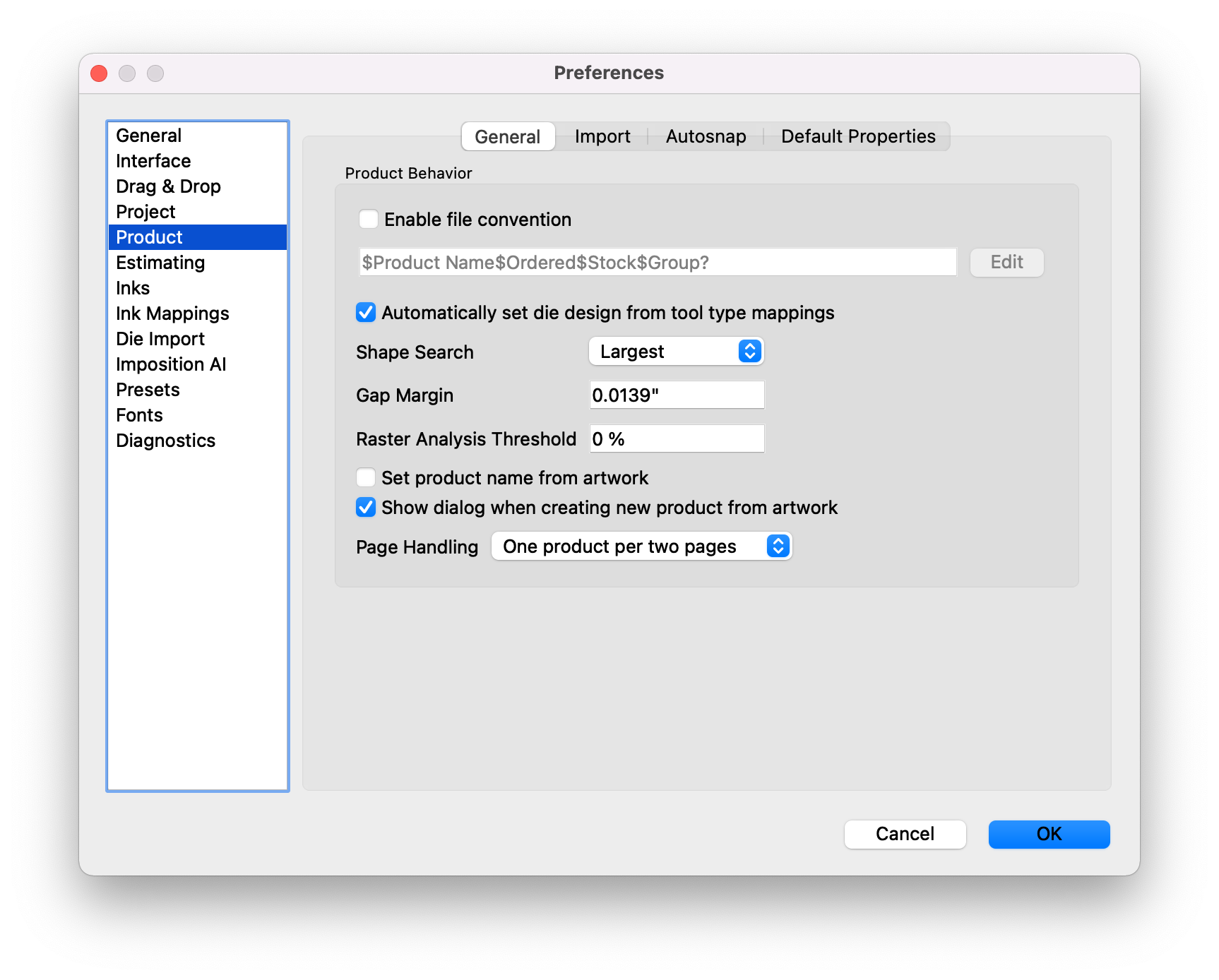
You can see in this Product view of the Preferences what the current file convention is configured to be. For example, in the screenshot above, the convention is as follows:
$Product Name$Ordered$Stock$Group?
This means that the filename will begin with a '$', and anything between the first $ and the second $ in the filename will be used as the Product Name. Anything between the second $ and third $ will be set to the Ordered quantity. Anything between the third $ and the fourth $ will be set to the Stock property. Finally, anything after the fourth $ will be set to the Group property. Notice that the convention has a ? after the "Group" text. This means that this value is optional, and may not appear in the filename. If it doesn't appear in the filename, nothing will be mapped to the Group property.
To edit and customize the file name convention, click on the Edit button:
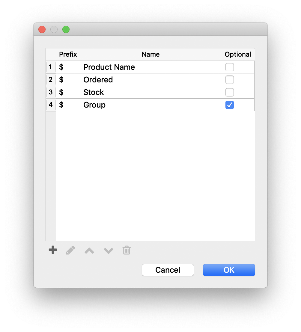
Here, we can add (+), remove (🗑), edit, and reorder the sections of the convention we are setting. You can also use different prefixes, so, for example, the filename could be $springwater#1500%PVC, where the product name is prefixed by $, the ordered quantity prefixed by #, and the stock prefixed by %.
You can choose any product property and even specify custom product properties to be set via file naming conventions. When done, click OK to return to the Preferences window, and OK again to save the Preference changes.
← Key Concepts Things →