# Working with the Griffin Switch App
tilia Griffin Auto packs many features into a single solution, giving you an automation toolbox for stepping up, image tracing, tiling, nesting, and ganging your artwork onto sheets or rolls and generating production ready output for your printers and cutters.
The tilia Griffin app gives you full access to the power of tilia Griffin Auto. This app contains over 300 properties. Detailed descriptions of all properties are found below. Each property also has detailed tooltips in Switch. We recommend utilizing them as you work with the app.
Almost all properties can be set using variables and script expressions to utilize the rich set of data available in Switch like job properties, folder hierarchies, metadata fields, and database entries.
# Inputs
The tilia Griffin app collects artwork files from a single input connection until certain trigger event(s) occur at which point the files are processed. The app supports PDF and PDF-based AI formats as well as TIFF, PNG, BMP, JPG, and GIF image formats.
The input handling logic is similar to the built-in "Assemble job" flow element. You can wait for N or more files to enter the input folder or wait N minutes after the first file has arrived. In Advanced mode you can also write a custom trigger condition, and control which artwork files are to be included together during processing by using a trigger identifier. More details about triggers are found in Advanced Mode, described in depth below.
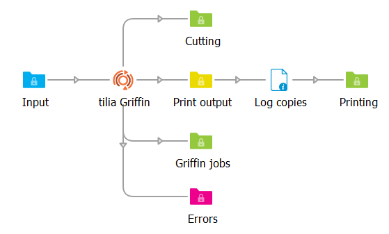
# Outgoing connection
In tilia Griffin app you can create as many outgoing connections as you like. For each connection you can choose whether to generate output files or to send along input files using the Data property.
# Output files
When selecting "Output files" for the Data property you are presented with options to output for printing, output for cutting, output job file. One or more of these options must be selected within a single connection to produce output.
Output for printing – Generates imposed PDF(s) of the layouts generated by Griffin. When enabled, there are properties to control whether to produce a single multi-page PDF or separate PDFs for each layout and whether to create a separate PDF page for each copy required. Other options include whether to remove tool paths from the original artwork and whether to use PDF 1.6 UserUnit for layouts above 200 inches in width or height.
Output for cutting – Generates vector PDF, DXF, or Zund Cut Center (ZCC) cutting output containing all tool paths in the imposed layout(s). For PDF output, you can choose whether to generate a single cutting file containing all generated layouts, or individual PDF files for each layout. Other options include which marks to include in output and how to map tool types to colors and layer names.
Output job file – When enabled, a Griffin job file, GFN, will be created. This allows you to open the job in the tilia Griffin desktop application to do further adjustments to layouts if needed. This option is also useful for archiving the generated layouts for future reprint or revision update.
XML dataset name - The app will attach an external XML dataset to each file created on the given output files connection. This XML data contains information about how many layout copies are required to produce, which artwork files were placed on each layout, and other statistics about each layout like sheet usage. The XML dataset name property allows you to customize the name of this dataset.
For a full list of all Output files properties and their descriptions, please refer to Output files properties.
# Input files
When selecting "Input files" for the Data property you can select which scenario you want to send input files through this connection via the Move property.
The most common usage is "On error". When this option is selected, only input files that could not be placed in layouts are sent to this connection. The most common scenario is artwork files that are too big to fit on the board or roll. If no "On error" connection has been setup, these input files are sent to the Problem jobs folder. In either scenario, the error is logged in Messages.
"On success" connections will only send input files that were successfully placed in layouts.
"Always" connections will send along all input files regardless of success or failure. Note that error situations are still logged as errors in Messages.
If there are no matching input files connections for a given input file, it will be deleted, i.e. sent to null.
# Basic Mode
With so much functionally packed into the app, there are over 220 flow element properties total. To make it easy to get started with the app, there are two modes to choose from: Basic and Advanced.
Basic mode provides a minimal set of 12 high-level properties. Even with this limited subset, you can create print-ready layouts on rolls or boards while controlling rotation, sheet margins, and the cutting tool paths. You can also include and customize dynamic barcodes, camera marks, and text marks. For a full list of all Basic mode properties and their descriptions, please refer to Basic mode properties.
Basic mode always performs free nesting appropriate for cutting tables. Barcodes are always placed in the upper-left corner of the layout while text marks are placed in the center of the top edge. There is some control over mark content while Advanced mode provides many more properties.
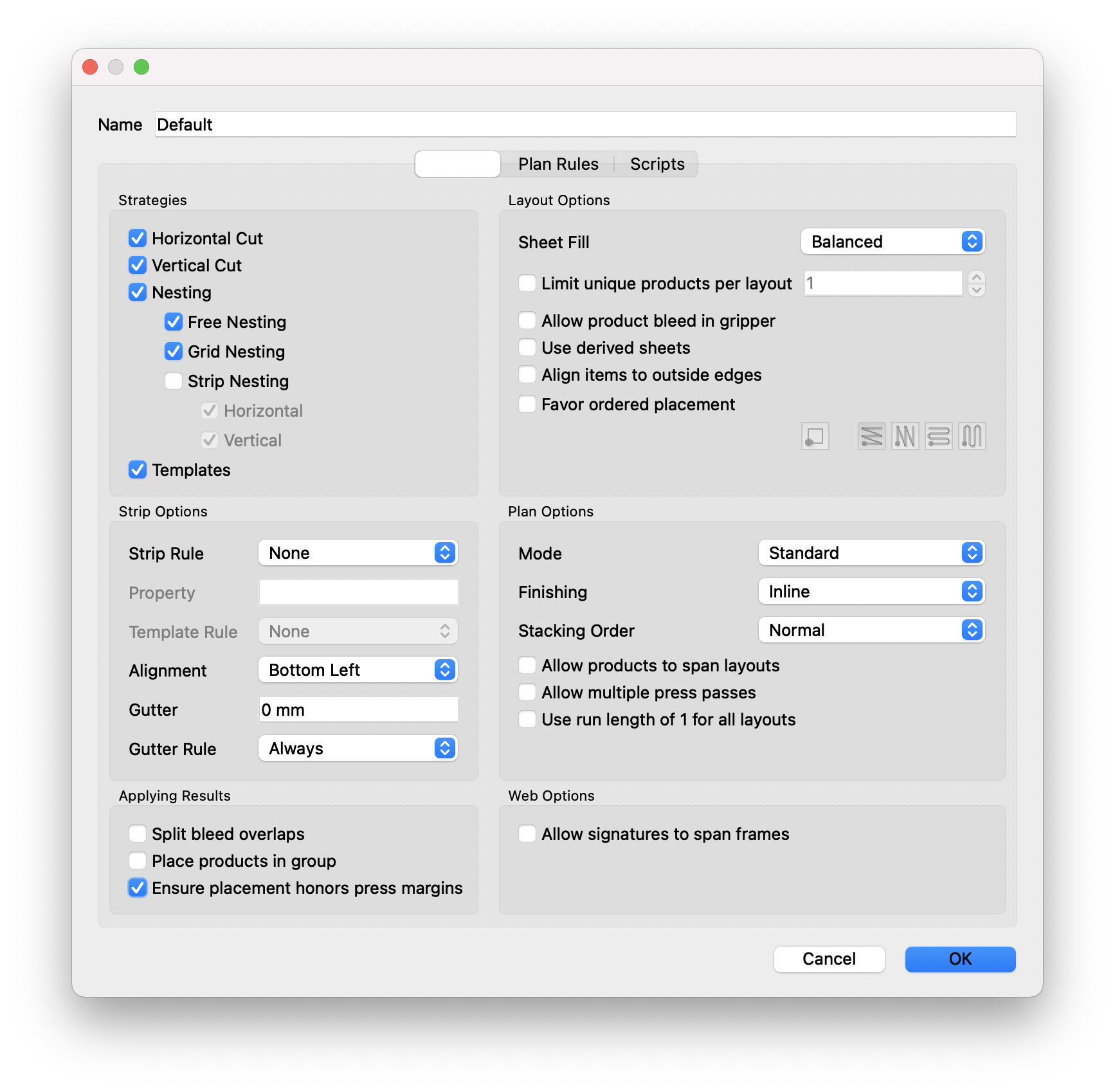
# Advanced Mode
Due to the number of limitations in Basic mode, most users will opt to use Advanced mode instead which gives you full control of all features in the tillia Griffin app. Below is a list of Advanced mode capabilities beyond what is possible in Basic mode:
- Artwork tiling
- Artwork scaling
- Image tracing for automatic cut line generation
- Artwork and board flutes directions
- Multi-page handling options
- Artwork front repeat or mirror to back
- Artwork barcode, text, fill, and grommet marks
- Nest for guillotine cutters or cutting tables
- Custom roll and board sizes
- Turn vs. tumble for double-sided layouts
- Custom trigger conditions
- Trigger identifiers to control which artwork files are processed together
- Up to four different tool types can be imported at a time
- Content margins defined independently for each sheet edge
- Options to control artwork bleed clipping path offsets and spacing
- Mark position and other mark customization options
Advanced mode properties are classified into three categories - Trigger conditions, Layout properties, and Artwork properties. Each category is represented by a read-only property with all related properties defined as child nodes of the property.
# Trigger conditions
Trigger conditions define when artwork files being collected in the input folder are processed by Griffin. You can trigger processing when N or more files arrive, N minutes after the first file has arrived, or on a custom trigger condition. You can also control which artwork files are to be included together during processing by using a Trigger identifier.
When multiple trigger condition properties are configured, the first trigger event that occurs will cause all input jobs with the same trigger identifier value to be processed.
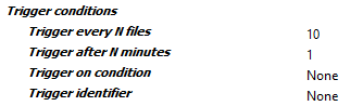
Trigger every N files The total number of artwork files needed before starting processing in Advanced mode. An empty or 0 value disables this option.
Trigger after N minutes Start processing current set of artwork pieces N minutes after first artwork arrived in Advanced mode regardless of whether required number of artwork pieces has been reached. An empty or 0 value disables this option.
Trigger on condition Processing is started whenever this condition is true regardless of whether N files or N minutes rules have been met. This condition is re-evaluated for each new job in the context of that job. A value of None means this option is disabled.
Trigger identifier A string value evaluated in the context of each incoming job that determines which artwork files should be processed together. If set, Griffin will include only jobs with the same Trigger Identifier and the "Trigger every N files" and "Trigger after N minutes" properties will only consider other jobs with the same Trigger identifier value when determining whether procesing should start. A value of None means this option is disabled.
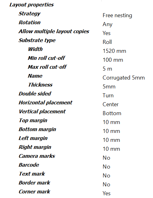
# Layout properties
Layout properties control how artwork pieces are placed on layouts, substrate type and sizes, double sided handling, margins, and layout placement.
Strategy dictates the kind of layouts that are created. "Free nesting" is the most aggressive nesting strategy and is ideal for cutting tables. "Grid nesting" also nests irregular shapes while keeping same shaped items together on the sheet in step and repeat groups. "Guillotine" will place pieces in strips that can be cut out with a guillotine cutter.
Rotation along with Flutes for board substrates and the Flutes property in Artwork properties control the allowed rotations for artwork pieces in the layout. "Any" rotation lets artwork pieces be placed at any angle unless the artwork and board both have flutes directions in which case only rotations that align flutes directions are allowed. "Orthogonal" rotation allows 0, 90, 180, and 270 degree rotations unless flutes need to be honored. "None" rotation will ensure that artwork pieces are not rotated on the layout.
Layout properties also include the option to add Camera, Barcode, Text, Border, and Corner marks, each with several child properties controlling mark content, placement, and color. Barcode and text mark have options for using dynamic keywords.
# Strategy
Type of nested layouts to generate.
# First cut
Direction of first cut for guillotine cutting.
# Rotation
Type of rotation allowed for this artwork piece during nesting in Advanced mode. If artwork has flutes direction, then rotation will be further restricted to match flutes with substrate grain direction.
# Allow multiple layout copies
Whether to allow multiple copies of layouts generated by the nesting tool.
# Substrate type
Type of substrate to nest onto: Board or Roll.
# Width
Width of board or roll to nest artwork onto.
# Height
Height of board to nest artwork onto.
# Flutes
Flutes direction of board if any. Long means flutes run in the direction of the long edge of the board, while Short means flutes run along the short edge of the board.
# Min roll cut-off
Min roll cutoff height.
# Max roll cut-off
Max roll cutoff height.
# Name
Optional name of substrate used in reporting and Zund Cut Center (ZCC) cutting output.
# Thickness
Optional substrate thickness. Thickness is included in reporting and Zund Cut Center (ZCC) cutting output to automatically match the substrate with the corresponding material in Zund Cut Center.
# Double sided
Workstyle when handling double-sided work.
# Horizontal placement
Horizontal position on the layout to align nested artwork pieces.
# Vertical placement
Vertical position on the layout to align nested artwork pieces.
# Top margin
Amount of space on top edge of layout to ensure that no artwork pieces are placed into in Advanced mode.
# Bottom margin
Amount of space on bottom edge of layout to ensure that no artwork pieces are placed into in Advanced mode.
# Left margin
Amount of space on left edge of layout to ensure that no artwork pieces are placed into in Advanced mode.
# Right margin
Amount of space on right edge of layout to ensure that no artwork pieces are placed into in Advanced mode.
# Camera marks
Whether or not to add camera marks to each generated layout in Advanced mode
# Shape
Shape of the camera marks: circle or cross.
# Stroke color
Camera mark stroke color.
# Cyan
Cyan component of custom color from 0 to 100 for camera mark stroke color.
# Magenta
Magenta component of custom color from 0 to 100 for camera mark stroke color.
# Yellow
Yellow component of custom color from 0 to 100 for camera mark stroke color.
# Black
Black component of custom color from 0 to 100 for camera mark stroke color.
# Spot name
Optional spot name for camera mark stroke color. When specified, this custom color is treated as a spot color instead of a process color.
# Stroke thickness
Camera mark stroke thickness.
# Fill color
Camera mark fill color.
# Cyan
Cyan component of custom color from 0 to 100 for camera mark fill color.
# Magenta
Magenta component of custom color from 0 to 100 for camera mark fill color.
# Yellow
Yellow component of custom color from 0 to 100 for camera mark fill color.
# Black
Black component of custom color from 0 to 100 for camera mark fill color.
# Spot name
Optional spot name for camera mark fill color. When specified, this custom color is treated as a spot color instead of a process color.
# Size
The size of each camera mark instance.
# Layer
Optional layer name for this camera mark. When specified, the mark's content will be placed in a PDF layer with the given name during export.
# Min distance
The minimum distance to place camera marks from the shape of items in the layout.
# Add corners
Whether to place camera marks in the four corners of the layout.
# Double corner
Whether to include a second corner mark in the lower-right corner of the layout. If enabled, the second corner mark is placed to the left of the right corner mark by the double corner offset.
# Double corner offset
Distance to place the second corner mark from the lower-right corner mark.
# Margins
Use 'Layout margins' to ensure camera marks are not placed outside the allowed content region of the layout.
Use 'Custom margins' to define custom distances from each sheet edge where camera marks can be placed.
# Top margin
Custom distance from top sheet edge where camera marks can be placed.
# Bottom margin
Custom distance from bottom sheet edge where camera marks can be placed.
# Left margin
Custom distance from left sheet edge where camera marks can be placed.
# Right margin
Custom distance from right sheet edge where camera marks can be placed.
# Mirror to back
When enabled, camera marks are automatically mirrored to the back side of the layout. This is useful for cases when the layout will be getting cut face down on the cutting table.
# Auto distribute
Mode to use to automatically place camera marks throughout the layout. When set to 'None', only corner camera marks are placed.
'Spacing' mode uses a minimum spacing distance while 'Quantity' mode adds a specific number of marks.
# Quantity
The desired number of auto-distributedcamera marks to place in layouts in Advanced mode. This quantity is not guaranteed since there are situations where space is too limited.
# Min spacing
The minimum distance allowed between auto-distributed camera marks when auto distribute mode is set to 'Spacing'.
# Barcode
Whether or not to add a barcode mark to each generated layout in Advanced mode.
# Fill color
Layout barcode color.
# Cyan
Cyan component of custom color from 0 to 100 for layout barcode fill color.
# Magenta
Magenta component of custom color from 0 to 100 for layout barcode fill color.
# Yellow
Yellow component of custom color from 0 to 100 for layout barcode fill color.
# Black
Black component of custom color from 0 to 100 for layout barcode fill color.
# Spot name
Optional spot name for layout barcode color. When specified, this custom color is treated as a spot color instead of a process color.
# Layer
Optional layer name for this layout barcode. When specified, the mark's content will be placed in a PDF layer with the given name during export.
# Format
Layout barcode format type.
# Show human-readable
If enabled, plain text of the barcode content is included below the barcode for 1D barcode formats such as Code 39 and Code 128.
# Data
Dynamic keyword for barcode content or any custom text when using the 'Custom' option in Advanced mode.
Each keyword option has a corresponding text value that can be used and combined in the custom text value:
Layout name: <layout.name>
Layout index: <layout.index>
Layout dimensions: <layout.dimensions>
Layout width: <layout.width>
Layout height: <layout.height>
Layout copies: <layout.copies>
Layout current copy: <layout.copy>
Layout side: <layout.side>
Layout random ID: <layout.random>
Layout placed: <layout.placed>
Layout waste: <layout.waste>
Job ID: <job.id>
Date ISO format: <date.iso>
Date long format: <date.long>
Date medium format: <date.medium>
Date short format: <date.short>
Time ISO format: <time.iso>
Time long format: <time.long>
Time medium format: <time.medium>
Time short format: <time.short># Custom value
Text content of this layout barcode mark which can include multiple keywords like <job.id> and <layout.index>.
# Scale
Scale factor to apply to the layout barcode to increase or decrease its size. The default value of 1.0 signifies 100% meaning no scaling is performed on the barcode.
# Mark reference point
Reference point in this layout barcode to align layout placement point to.
# Layout reference point
Point within layout to place barcode mark alignment point to.
# Horizontal offset
Additional horizontal offset to move the layout barcode from the placement point.
Positive scalar values move the barcode to the right while negative values move the barcode to the left within the layout.
# Vertical offset
Additional vertical offset to move the layout barcode from the placement point.
Positive scalar values move the barcode up while negative values move the barcode down within the layout.
# Rotation
Rotation of barcode in the layout.
# Text mark
Whether or not to add a text mark to each generated layout.
# Color
Layout text mark color.
# Cyan
Cyan component of custom color from 0 to 100 for layout text mark.
# Magenta
Magenta component of custom color from 0 to 100 for layout text mark.
# Yellow
Yellow component of custom color from 0 to 100 for layout text mark.
# Black
Black component of custom color from 0 to 100 for layout text mark.
# Spot name
Optional spot name. When specified, this custom layout text mark color is treated as a spot color instead of a process color.
# Layer
Optional layer name for this layout text mark. When specified, the mark's content will be placed in a PDF layer with the given name during export.
# Text
Dynamic keyword for layout text content or any custom text when using the 'Custom' option in Advanced mode.
Each keyword option has a corresponding text value that can be used and combined in the custom text value:
Layout name: <layout.name>
Layout index: <layout.index>
Layout dimensions: <layout.dimensions>
Layout width: <layout.width>
Layout height: <layout.height>
Layout copies: <layout.copies>
Layout current copy: <layout.copy>
Layout side: <layout.side>
Layout random ID: <layout.random>
Layout placed: <layout.placed>
Layout waste: <layout.waste>
Job ID: <job.id>
Date ISO format: <date.iso>
Date long format: <date.long>
Date medium format: <date.medium>
Date short format: <date.short>
Time ISO format: <time.iso>
Time long format: <time.long>
Time medium format: <time.medium>
Time short format: <time.short># Custom value
Content of layout text mark which can include multiple keywords like <job.id> and <layout.index>.
# Font
Name of font to use in this layout text mark. Use 'Select from library' to view a list of available fonts.
# Font size
Size of text in points (pt) for this layout text mark.
# Font style
Font style of layout text mark. Note that some fonts do not support all styles. When a style is chosen that is not available for the given font, the style will default to Normal and a warning message will be logged in Switch.
# Mark reference point
Reference point in this layout text mark to align layout placement point to.
# Layout reference point
Point within layout to place layout text mark alignment point to.
# Horizontal offset
Additional horizontal offset to move the layout text mark from the placement point. Positive scalar values move the mark to the right while negative values move the mark to the left within the layout.
# Vertical offset
Additional vertical offset to move the mark from the placement point.
Positive scalar values move the layout text mark up while negative values move the mark down within the layout.
# Rotation
Rotation of layout text mark within layout.
# Border mark
Whether or not to add a border mark to each generated layout.
# Stroke color
Camera mark stroke color.
# Cyan
Cyan component of custom color from 0 to 100.
# Magenta
Magenta component of custom color from 0 to 100.
# Yellow
Yellow component of custom color from 0 to 100.
# Black
Black component of custom color from 0 to 100.
# Spot name
Optional spot name. When specified, this custom color is treated as a spot color instead of a process color.
# Stroke thickness
Stroke thickness of border lines.
# Fill color
Border mark fill color.
# Cyan
Cyan component of custom color from 0 to 100.
# Magenta
Magenta component of custom color from 0 to 100 for artwork fill mark color.
# Yellow
Yellow component of custom color from 0 to 100.
# Black
Black component of custom color from 0 to 100.
# Spot name
Optional spot name. When specified, this custom color is treated as a spot color instead of a process color.
# Layer
Optional layer name for this border mark. When specified, the mark's content will be placed in a PDF layer with the given name during export.
# Top
Distance from the top edge of the sheet in the downward direction to draw the top edge of the border mark.
# Bottom
Distance from the bottom edge of the sheet in the upward direction to draw the bottom edge of the border mark.
# Left
Distance from the left edge of the sheet in the right direction to draw the left edge of the border mark.
# Right
Distance from the right edge of the sheet in the left direction to draw the right edge of the border mark.
# Corner mark
Whether or not to add a corner mark to each generated layout.
# Stroke color
Corner mark stroke color.
# Cyan
Cyan component of custom color from 0 to 100.
# Magenta
Magenta component of custom color from 0 to 100.
# Yellow
Yellow component of custom color from 0 to 100.
# Black
Black component of custom color from 0 to 100.
# Spot name
Optional spot name. When specified, this custom color is treated as a spot color instead of a process color.
# Stroke thickness
Stroke thickness of corner mark lines.
# Layer
Optional layer name for this layout corner mark. When specified, the mark's content will be placed in a PDF layer with the given name during export.
# Corner type
Corner mark flavors: Type 1 or Type 2. Both types are simple "L" shaped stroked marks, with Type 1 corner marks facing towards the layout and Type 2 facing outwards.
# Width
Width of each corner mark, i.e. the distance from the corners to extend the horizontal lines.
# Height
Height of each corner mark, i.e. the distance from the corners to extend the vertical lines.
# Horizontal distance
Optional distance to offset the corner mark in the horizontal direction. Positive values will move the corner point away from the layout while negative values will move the corner point inside the layout.
# Vertical distance
Optional distance to offset the corner mark in the vertical direction. Like Horizontal Distance, positive values will move the corner point away while negative values with move the corner point inside the layout.
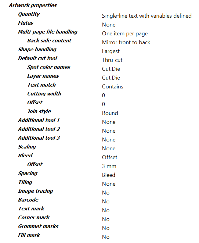
# Artwork properties
Artwork properties control how each individual artwork file is handled in Griffin. Here you can define the order quantity, flutes direction, cutting tools mappings from PDF paths, bleed mask offsets, and placement spacing.
You can also optionally scale the artwork using the Scaling property. Scaling can be defined as a percentage of the original size or a fixed size.
Artwork properties also include the Multi-page file handling property that allows you to control how to interpret multi-page artwork files. "One item per two pages" will interpret even numbered pages as the back side content of the previous page. "One item per page" will treat each page as a different single-sided artwork piece and gives you the option of duplicating the artwork to the back or mirroring the front to the back with the Back side content child property.
Artworks properties also include the options to add a Barcode, Text, Corner, Grommet, and Fill marks to the artwork. Like layout marks, each mark type has several child properties controlling content, placement, and color. For a full list of all Advanced mode artwork properties and their descriptions, please refer to Advanced Mode Properties - Artwork Properties.
# Quantity
Order quantity for this artwork.
# Flutes
Flutes direction of this artwork if any.
# Multi-page file handling
This option affects how multi-page artwork files are interpreted. If "One product per file" is selected, a single artwork piece is always created for each artwork file regardless of the number of pages. If "One product per page" is selected, one single-sided artwork piece is created for each page in the artwork file. If "One double-sided product every two pages" is selected, an artwork piece will be created for every two pages with the first page used as the front artwork and the second page used as the back artwork of the artwork piece. If the artwork file has an odd number of pages, the last page will create a single-sided piece. For example, if a 5 page PDF file comes in, this option will create 2 double-sided artwork pieces and 1 single-sided piece. Pages 1 and 2 will be used as the front and back of the first artwork piece respectively and pages 3 and 4 used as the front and back of the second piece. Page 5 will be used as the front of the final single-sided piece.
# Back side content
Content to use for back side if any. Front artwork can be duplicated on back or mirrored to back.
# Shape handling
Shape handling mode to use when finding closed path shapes from the dielines in the artwork. 'Multiple' mode will create a new artwork item for each closed path shape detected in the artwork.
# Default cut tool
Main tool being used to cut artwork item.
# Spot color names
List of names to match with spot color names in the artwork that define paths for default cut tool type. Matching is case insensitive.
# Layer names
List of names to match with layer names in the artwork that identify paths for default cut tool type. Matching is case insensitive.
# Text match
Type of text matching to use for default cut tool. 'Equals' matches the text exactly with the spot or layer name, 'StartsWith' matches the text with the beginning of the name, and 'Contains' matches the text with any portion of the name.
# Cutting width
Width of the main cutting tool. This property can be used to define the spacing distance between items the Nesting Tool uses when the artwork item spacing type is set to 'Tool' to ensure the cutting tool does not affect other items in the layout.
# Offset
Optional scalar offset to apply to the shape for the default cut tool. Negative offset values will cause the shape to be reduced while positive values will increase the shape size.
# Join style
The style used to join path segments in the shape when a cutting offset is applied for the default cut tool.
# Miter limit
For Cut category tools with a cutting offset and 'Miter' join style, this limit defines the distance beyond the end of the joined path segments where mitering is clipped to avoid long spikes on sharp corners.
# Additional tool 1
Optional tool to define in addition to the default cut tool when more than one tool is used with the artwork. The following tools are available to choose from. Cutting tools have additional properties for defining cutting width, path offsets, and path ofset join styles. Cutting tools: Cut, Thru-cut, Kiss-cut, V-cut, Bevel-cut, Route, Laser, Drill, Punch Creasing tools: Crease General tools: Score, Engrave, Burn
# Spot color names
List of names to match with spot color names in the artwork that define paths for additional tool 1 type. Matching is case insensitive.
# Layer names
List of names to match with layer names in the artwork that identify paths for additional tool 1 type. Matching is case insensitive.
# Text match
Type of text matching to use for additional tool 1. 'Equals' matches the text exactly with the spot or layer name, 'StartsWith' matches the text with the beginning of the name, and 'Contains' matches the text with any portion of the name.
# Cutting width
For 'Cut' category tools, the width of the cutting tool for additional tool 1. This property can be used to define the spacing distance between items the Nesting Tool uses when the artwork item spacing type is set to 'Tool' to ensure the cutting tool does not affect other items in the layout.
# Offset
Optional scalar offset to apply to the shape for additional tool 1. Negative offset values will cause the shape to be reduced while positive values will increase the shape size.
# Join style
For Cut category tools, the style used to join path segments in the shape when a cutting offset is applied for additional tool 1.
# Miter limit
For Cut category tools with a cutting offset and 'Miter' join style, this limit defines the distance beyond the end of the joined path segments where mitering is clipped to avoid long spikes on sharp corners.
# Additional tool 2
Optional second tool to define in addition to the default cut tool when more than one tool is used with the artwork. The following tools are available to choose from. Cutting tools have additional properties for defining cutting width, path offsets, and path ofset join styles. Cutting tools: Cut, Thru-cut, Kiss-cut, V-cut, Bevel-cut, Route, Laser, Drill, Punch Creasing tools: Crease General tools: Score, Engrave, Burn
# Spot color names
List of names to match with spot color names in the artwork that define paths for additional tool 2 type. Matching is case insensitive.
# Layer names
List of names to match with layer names in the artwork that identify paths for additional tool 2 type. Matching is case insensitive.
# Text match
Type of text matching to use for additional tool 2. 'Equals' matches the text exactly with the spot or layer name, 'StartsWith' matches the text with the beginning of the name, and 'Contains' matches the text with any portion of the name.
# Cutting width
For 'Cut' category tools, the width of the cutting tool for additional tool 2. This property can be used to define the spacing distance between items the Nesting Tool uses when the artwork item spacing type is set to 'Tool' to ensure the cutting tool does not affect other items in the layout.
# Offset
Optional scalar offset to apply to the shape for additional tool 2. Negative offset values will cause the shape to be reduced while positive values will increase the shape size.
# Join style
For Cut category tools, the style used to join path segments in the shape when a cutting offset is applied for additional tool 2.
# Miter limit
For Cut category tools with a cutting offset and 'Miter' join style, this limit defines the distance beyond the end of the joined path segments where mitering is clipped to avoid long spikes on sharp corners.
# Additional tool 3
Optional third tool to define in addition to the default cut tool when more than one tool is used with the artwork. The following tools are available to choose from. Cutting tools have additional properties for defining cutting width, path offsets, and path ofset join styles. Cutting tools: Cut, Thru-cut, Kiss-cut, V-cut, Bevel-cut, Route, Laser, Drill, Punch Creasing tools: Crease General tools: Score, Engrave, Burn
# Spot color names
List of names to match with spot color names in the artwork that define paths for additional tool 3 type. Matching is case insensitive.
# Layer names
List of names to match with layer names in the artwork that identify paths for additional tool 3 type. Matching is case insensitive.
# Text match
Type of text matching to use for additional tool 3. 'Equals' matches the text exactly with the spot or layer name, 'StartsWith' matches the text with the beginning of the name, and 'Contains' matches the text with any portion of the name.
# Cutting width
For 'Cut' category tools, the width of the cutting tool for additional tool 3. This property can be used to define the spacing distance between items the Nesting Tool uses when the artwork item spacing type is set to 'Tool' to ensure the cutting tool does not affect other items in the layout.
# Offset
Optional scalar offset to apply to the shape for additional tool 3. Negative offset values will cause the shape to be reduced while positive values will increase the shape size.
# Join style
For Cut category tools, the style used to join path segments in the shape when a cutting offset is applied for additional tool 3.
# Miter limit
For Cut category tools with a cutting offset and 'Miter' join style, this limit defines the distance beyond the end of the joined path segments where mitering is clipped to avoid long spikes on sharp corners.
# Scaling
Whether to scale the artwork to make the content and shape bigger or smaller. Scaling can be defined by percentage of original artwork shape size or by specific dimensions.
# Width
Horizontal scaling defined as percent of original artwork width. For example, 50% is half of the original artwork shape width while 100% results in no scaling. Percent sign '%' is not required.
# Height
Vertical scaling defined as percent of original artwork height. For example, 50% is half of the original artwork shape height while 100% results in no scaling. Percent sign '%' is not required.
# Width
The desired width of the artwork content. When width differs from the original content width of the front-side artwork, the artwork piece is scaled automatically in the horizontal direction to match this width.
# Height
The desired height of the artwork content. When height differs from the original content height of the front-side artwork, the artwork piece is scaled automatically in the vertical direction to match this height.
# Scale proportionally
When either width or height are not specified, this property controls whether the unspecified dimension is scaled proportionally to the other dimension. When turned off, only the dimension that is specified is scaled.
# Bleed
Type of bleed mask to apply to this artwork piece's content. "Offset" creates a uniform offset path from the artwork piece shape. "None" will not apply a bleed mask.
# Offset
Offset from artwork piece shape to generate bleed clipping mask with. As with all other scalar value properties, units may be specified (e.g. 3mm) and if omitted, the default units are assumed.
# Spacing
Artwork piece spacing type used when placing piece in layouts during nesting.
# Offset
Spacing offset to apply to artwork piece shape when "Offset" spacing type is used. As with all other scalar value properties, units may be specified (e.g. 3mm) and if omitted, the default units are assumed.
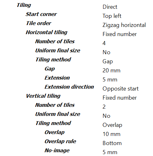
# Tiling
Tilia mode for artwork: None or Direct. None disables tiling while Direct mode allows you to define properties to control tiling behavior in the horizontal and vertical directions.
# Start corner
The corner of the artwork where the first tile is to be placed. This property plus tile order define the exact order tiles are to be placed.
# Tile order
Tile placement order. This property plus start corner define the exact order tiles are to be placed.
# Horizontal tiling
Rule for splitting up artwork into tiles in the horizontal direction. Used to divide the artwork into multiple items to be produced separately.
# Number of tiles
Number of tiles to create in the horizontal direction. Tiles are evenly spaced across the width of the artwork.
# Uniform final size
When defining a fixed number of tiles, enabling this option ensures the final tile sizes are uniform in the horizontal direction regardless of gap or overlap settings. When not enabled, inner and edge tile sizes can differ because uniform tile sizes are then calculated before gap or overlap rules are applied.
# Tile width
Fixed width of tiles in horizontal direction.
# Tile widths
List of all tile widths in the horizontal direction.
# Tiling method
Tiling method to use in horizontal direction in any: Gap or Overlap.
# Gap
Gap distance between tiles in the horizontal direction.
# Extension
Amount of extra artwork content beyond the tile gap edge to extend in the horizontal direction.
# Extension direction
Rule defining which horizontal direction(s) the gap is extended for each tile.
# Overlap
Distance beyond tile edge to extend the tile horizontally to create overlap.
# Overlap rule
Rule defining what horizontal edge(s) of tiles will overlap with neighboring tiles.
# No-image
Width of the section at the end of the overlap where no artwork content is allowed. This no image section can be used for example to create a glue strip area on the tile piece.
# Vertical tiling
Rule for splitting up artwork into tiles in the vertical direction. Used to divide the artwork into multiple items to be produced separately.
# Number of tiles
Number of tiles to create in the vertical direction. Tiles are evenly spaced across the height of the artwork.
# Uniform final size
When defining a fixed number of tiles, enabling this option ensures the final tile sizes are uniform in the vertical direction regardless of gap or overlap settings. When not enabled, inner and edge tile sizes can differ because uniform tile sizes are then calculated before gap or overlap rules are applied.
# Tile height
Fixed height of tiles in vertical direction.
# Tile heights
List of all tile heights in the vertical direction.
# Tiling method
Tiling method to use in vertical direction if any: Gap or Overlap.
# Gap
Gap distance between tiles in the vertical direction.
# Extension
Amount of extra artwork content beyond the tile gap edge to extend in the vertical direction.
# Extension direction
Rule defining which vertical direction(s) the gap is extended for each tile.
# Overlap
Distance beyond tile edge to extend the tile vertically to create overlap.
# Overlap rule
Rule defining what vertical edge(s) of tiles will overlap with neighboring tiles.
# No-image
Height of the section at the end of the overlap where no artwork content is allowed. This no image section can be used for example to create a glue strip area on the tile piece.
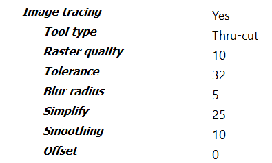
# Image tracing
Whether to perform image tracing on the artwork to automatically generate precise cut paths around artwork content.
# Tool type
Name of cutting tool to use for the generated cut tool path.
# Raster quality
Quality of the raster image to use for generating the cut tool path from 1 to 100. A value of 100 (i.e. 100%) will rasterize the image at full size up to a limit of 10 megapixels. Lower values will scale the image down for faster processing and in some case preferred results as less detail is used for tracing.
# Tolerance
Amount of color difference to allow before adjacent colors are considered different. A value of 0 means no tolerance in color differences is allowed while 100 is the maximum allowed tolerance in color differences.
# Blur radius
The amount of blurring to apply to edges that are encountered during edge detection between 0 and 100. A higher blur radius means more blurring is applied during edge detection which can lead to less jagged paths.
# Simplify
The amount of simplification to apply to the generated path. Simplify works by removing points on the path that are within a certain tolerance. A value of 0 disables path simplification while a value of 100 will use the highest allowed tolerance when removing points.
# Smoothing
Smoothing converts individual points on the generated path to Bezier curves to produce smoother paths. A value of 0 disables path smoothing while a value of 100 will perform the most aggressive path curve smoothing.
# Offset
Additional offset distance to expand the generated path.
# Barcode
Whether or not to add a barcode to this artwork piece.
# Fill color
Artwork barcode color.
# Cyan
Cyan component of custom color from 0 to 100 for artwork barcode fill color.
# Magenta
Magenta component of custom color from 0 to 100 for artwork barcode fill color.
# Yellow
Yellow component of custom color from 0 to 100 for artwork barcode fill color.
# Black
Black component of custom color from 0 to 100 for artwork barcode fill color.
# Spot name
Optional spot name for artwork barcode color. When specified, this custom color is treated as a spot color instead of a process color.
# Layer
Optional layer name for this artwork barcode. When specified, the mark's content will be placed in a PDF layer with the given name during export.
# Format
Artwork barcode format type.
# Show human-readable
If enabled, plain text of the artwork barcode content is included below the barcode for 1D barcode formats such as Code 39 and Code 128.
# Data
Dynamic keyword for artwork barcode content or any text when using the 'Custom' option. Each keyword option has a corresponding text value that can be used and combined in the custom text value: Artwork name: <artwork.name> Artwork quantity: <artwork.quantity> Artwork width: <artwork.width> Artwork height: <artwork.height> Artwork path: <artwork.path> Artwork page number: <artwork.page-number> Artwork page count: <artwork.page-count> Job ID: <job.id> Date ISO format: <date.iso> Date long format: <date.long> Date medium format: <date.medium> Date short format: <date.short> Time ISO format: <time.iso> Time long format: <time.long> Time medium format: <time.medium> Time short format: <time.short>
# Custom value
Content of artwork barcode which can include keywords like <job.id> and <artwork.name>.
# Scale
Scale factor to apply to the artwork barcode to increase or decrease its size. The default value of 1.0 signifies 100% meaning no scaling is performed on the barcode.
# Mark reference point
Reference point in this artwork barcode to align artwork placement point to.
# Artwork reference point
Point within artwork to place barcode mark alignment point to
# Horizontal offset
Additional horizontal offset to move the artwork barcode from the placement point. Positive scalar values move the mark to the right while negative values move the mark to the left within the artwork.
# Vertical offset
Additional vertical offset to move the artwork barcode from the placement point. Positive scalar values move the barcode up while negative values move the barcode down within the artwork.
# Rotation
Rotation of barcode in the artwork.
# Text mark
Whether or not to add a text mark to this artwork piece.
# Color
Artwork text mark color.
# Cyan
Cyan component of custom color from 0 to 100 for artwork text mark color.
# Magenta
Magenta component of custom color from 0 to 100 for artwork text mark color.
# Yellow
Yellow component of custom color from 0 to 100 for artwork text mark color.
# Black
Black component of custom color from 0 to 100 for artwork text mark color.
# Spot name
Optional spot name for artwork text mark color. When specified, this custom color is treated as a spot color instead of a process color.
# Layer
Optional layer name for this artwork text mark. When specified, the mark's content will be placed in a PDF layer with the given name during export.
# Text
Dynamic keyword for artwork text mark content or any custom text when using the 'Custom' option. Each keyword option has a corresponding text value that can be used and combined in the custom text value: Artwork name: <artwork.name> Artwork quantity: <artwork.quantity> Artwork width: <artwork.width> Artwork height: <artwork.height> Artwork path: <artwork.path> Artwork page number: <artwork.page-number> Artwork page count: <artwork.page-count> Job ID: <job.id> Date ISO format: <date.iso> Date long format: <date.long> Date medium format: <date.medium> Date short format: <date.short> Time ISO format: <time.iso> Time long format: <time.long> Time medium format: <time.medium> Time short format: <time.short>
# Custom value
Content of artwork text mark which can include multiple keywords like <job.id> and <artwork.name>.
# Font
Name of font to use in this artwork text mark. Use 'Select from library' to view a list of available fonts.
# Font size
Size of text in points (pt) for this artwork text mark.
# Font style
Font style of artwork text mark. Note that some fonts do not support all styles. When a style is chosen that is not available for the given font, the style will default to Normal and a warning message will be logged in Switch.
# Mark reference point
Reference point in this artwork text mark to align artwork placement point to.
# Artwork reference point
Point within artwork to place artwork text mark alignment point to.
# Horizontal offset
Additional horizontal offset to move the artwork text mark from the placement point. Positive scalar values move the mark to the right while negative values move the mark to the left within the artwork.
# Vertical offset
Additional vertical offset to move the artwork text mark from the placement point. Positive scalar values move the mark up while negative values move the mark down within the artwork.
# Rotation
Rotation of artwork text mark within artwork.
# Corner mark
Whether or not to add a corner mark to this artwork piece.
# Stroke color
Corner mark stroke color.
# Cyan
Cyan component of custom color from 0 to 100.
# Magenta
Magenta component of custom color from 0 to 100.
# Yellow
Yellow component of custom color from 0 to 100.
# Black
Black component of custom color from 0 to 100.
# Spot name
Optional spot name. When specified, this custom color is treated as a spot color instead of a process color.
# Stroke thickness
Stroke thickness of corner mark lines.
# Layer
Optional layer name for this artwork corner mark. When specified, the mark's content will be placed in a PDF layer with the given name during export.
# Corner type
Corner mark flavors: Type 1 or Type 2. Both types are simple "L" shaped stroked marks, with Type 1 corner marks facing towards the artwork and Type 2 facing outwards.
# Width
Width of each corner mark, i.e. the distance from the corners to extend the horizontal lines.
# Height
Height of each corner mark, i.e. the distance from the corners to extend the vertical lines.
# Horizontal distance
Optional distance to offset the corner mark in the horizontal direction. Positive values will move the corner point away from the artwork while negative values will move the corner point inside the artwork.
# Vertical distance
Optional distance to offset the corner mark in the vertical direction. Like Horizontal Distance, positive values will move the corner point away while negative values with move the corner point inside the artwork.
# Grommet marks
Whether or not to add grommet marks to this artwork piece.
# Stroke color
Artwork grommet mark color.
# Cyan
Cyan component of custom color from 0 to 100 for artwork grommet mark color.
# Magenta
Magenta component of custom color from 0 to 100 for artwork grommet mark color.
# Yellow
Yellow component of custom color from 0 to 100 for artwork grommet mark color.
# Black
Black component of custom color from 0 to 100 for artwork grommet mark color.
# Spot name
Optional spot name for artwork grommet mark color. When specified, this custom color is treated as a spot color instead of a process color.
# Stroke thickness
Stroke thickness of artwork grommet mark lines.
# Layer
Optional layer name for this mark. When specified, the mark's content will be placed in a PDF layer with the given name during export.
# Shape
Shape of each grommet mark.
# Size
Width and height of each grommet mark instance.
# Circle diameter
The diameter of the inner circle in Target shape grommet marks.
# Margin
The margin offset to place grommet marks from the bounds of the artwork.
# Hem
The width of the hem for artwork grommet marks.
# Marks on hem
If enabled, grommet marks are mirrored onto the hem so they line up when the edges are folded.
# Spacing type
This property controls how artwork grommet marks are distributed across the edges. 'Max spacing' will evenly place marks as far apart as possible up to the max spacing distance. 'Quantity' will place the exact number of marks defined in the horizontal and vertical quantity properties.
# Max spacing
Maximum distance to allow between artwork grommet mark instances within an edge.
# Horizontal quantity
The exact number of artwork grommet marks to place evenly on top and bottom edges.
# Vertical quantity
The exact number of artwork grommet marks to place evenly on left and right edges.
# Top edge
Whether to add grommet marks to the top edge of the artwork.
# Bottom edge
Whether to add grommet marks to the bottom edge of the artwork.
# Left edge
Whether to add grommet marks to the left edge of the artwork.
# Right edge
Whether to add grommet marks to the right edge of the artwork.
# Fill mark
Whether or not to add a fill mark to this artwork piece.
# Color
Fill mark color.
# Cyan
Cyan component of custom color from 0 to 100 for artwork fill mark color.
# Magenta
Magenta component of custom color from 0 to 100 for artwork fill mark color.
# Yellow
Yellow component of custom color from 0 to 100 for artwork fill mark color.
# Black
Black component of custom color from 0 to 100 for artwork fill mark color.
# Spot name
Optional spot name. When specified, this custom color is treated as a spot color instead of a process color.
# Layer
Optional layer name for this artwork fill mark. When specified, the mark's content will be placed in a PDF layer with the given name during export.
# Margin
Margin offset from the artwork piece shape to create the fill mark.
# Tiling
Artwork properties also include tiling options. To enable tiling, set the Tiling property to "Direct". You will see child properties controlling which corner of the artwork to start tiling and the order of the tiles flowing through the artwork.
In Griffin, you can control tiling separately in the horizontal and vertical directions. For example, you can specify a fixed number of tiles in the horizontal direction and a fixed tile size (or no tiling at all) in the vertical directions.
In both directions you can also optionally define gaps or overlaps between tiles. When tiling with gaps you can specify an extension distance from the gap. In overlap tiling you can control which tiles overlap each other and define a no image distance, e.g. glue areas.
# Image tracing
Image tracing options are also available in Artwork Properties. The image tiling feature automatically generates precise cut line paths around artwork contours in cases where no cut shape has been provided, saving you countless hours manually adding cutting paths to artwork.
Image tracing is designed to be very fast while producing high quality shape tracings and works equally well with artwork imported from image-based formats, PDF, and AI formats. There are multiple settings providing fine-grained control over contour generation.
# Outgoing Connection Properties
This section contains detailed descriptions of all outgoing connections properties in the tilia Griffin app.
# Data
Whether to send original input files or newly output files generated by tilia Griffin of finished layouts.
# Output files properties
# Output for printing
Whether to generate imposed printing PDF(s) of the nested layouts.
# Layout grouping
Controls whether this export action produces a single file with all the layouts (Single file), one file for each single- or double-sided layout (File per layout), or one file for each layout side (File per side).
# Page per copy
Whether to output duplicate pages for each copy of a layout when multiple copies option is enabled in nesting and layout contains multiple copies.
# Remove artwork tool paths
If enabled, original tool paths in the artwork content are removed in the printing PDF. Currently only tool paths defined as spot colors can be removed.
# Use PDF 1.6 'UserUnit'
Enable this option if you are working with layouts with dimensions over 200 inches (roughly 5 meters) and your RIP supports the PDF 1.6 'UserUnit' field to address size limitations in the PDF specification.
# Output for cutting
Cutting output format to generate for your cutting devices or None if not exporting for cutting.
# Layout grouping
Controls whether Output for cutting action produces a single file with all the layouts (Single file) or one file for each single- or double-sided layout (File per layout).
# DXF version
DXF version to use: R13 or 2007.
# DXF version > Encoding
For the older R13 DXF version you need to specify the character encoding to use during export via the Encoding setting. DXF version 2007 and above always uses UTF-8 encoding which supports all Unicode characters.
# Units
Which units to use in DXF path and dimensions data.
# Job name
The Job Name field in Zund Cut Center. You can use dynamic keywords to record properties from the current job or layout along with date and time.
# Cutting mode
The cutting mode to use in Zund Cut Center: Standard, Quality, or Speed.
# Include barcodes
Whether or not to include barcode marks in cutting output.
# Include border marks
Whether or not to include border marks in cutting output.
# Include camera marks
Whether or not to include camera marks in cutting output.
# Include corner marks
Whether or not to include corner marks in cutting output.
# Include fill marks
Whether or not to include fill marks in cutting output.
# Include grommet marks
Whether or not to include grommet marks in cutting output.
# Include text marks
Whether or not to include text marks in cutting output.
# Use PDF 1.6 'UserUnit'
Enable this option if you are working with layouts with dimensions over 200 inches (roughly 5 meters) and your cutting device supports the PDF 1.6 'UserUnit' field to address size limitations in the PDF specification.
# Tool mapping n
Nth tool to include in cutting output. If tool is 'None' then no tool is exported.
# Tool mapping n > Color
Color to use when exporting paths from the nth tool mapping.
# Tool mapping n > Color > Cyan
Cyan component of custom color from 0 to 100 for the nth tool mapping.
# Tool mapping n > Color > Magenta
Magenta component of custom color from 0 to 100 for the nth tool mapping.
# Tool mapping n > Color > Yellow
Yellow component of custom color from 0 to 100 for the nth tool mapping.
# Tool mapping n > Color > Black
Black component of custom color from 0 to 100 for the nth tool mapping.
# Tool mapping n > Color > Spot name
Optional spot name. When specified, this custom color is treated as a spot color instead of a process color.
# Tool mapping n > Layer
Optional layer name to place the nth tool mapping paths into.
# Output job file
Whether to include a saved Griffin job file (.gfn) allowing you to open the nested job in the Griffin desktop application later for further editing.
# XML dataset name
Name of XML report dataset that gets attached to each output file or job folder.
# Dealing with errors
There are a few different types of errors that can occur in the Griffin Switch App. The best way to find out what is causing an error is to look to the tilia Griffin log file, found here:
On Mac:
/Users/[user]/Library/Application Support/Enfocus/Switch Server/ScriptData/com.tilia.griffin.app/log/rolling.log
On PC:
C:\Users\[user]\AppData\Roaming\Enfocus\Switch Server\ScriptData\com.tilia.griffin.app\log\rolling.log
Most of the time, the log will point directly to the error. For instance:
'The license on this machine has been activated on another machine. Please activate a valid license in order to continue using tilia Griffin Auto on this machine.'
In any event, this log will be helpful in diagnosing the issue.