# Managing Libraries
Once you've learned the basics of tilia Griffin you will want to boost your productivity by custom tailoring the application to match your production environment. This is done by setting up your Substrates, Tool Types, Mark Presets, and Tiling Presets libraries.
# Substrates
Substrates represent the different kinds of media that you work with, the board or roll sizes that are available, and printing margins. In addition, you can define default nesting settings and mark presets for printing and cutting marks that you always use with the given substrate.
To add, edit, and remove substrates from your library, go to the Window menu and select 'Substrates'. This opens the substrates dialog containing a list of all substrates and their settings.
To add a new substrate, click on the plus (plus) icon below the list of substrates on the left side of the dialog. In Griffin Go, which does not have roll support, a board-based substrate will be added. In Griffin, a menu will appear allowing you to choose between 'Board-based Substrate' and 'Roll-based Substrate'.
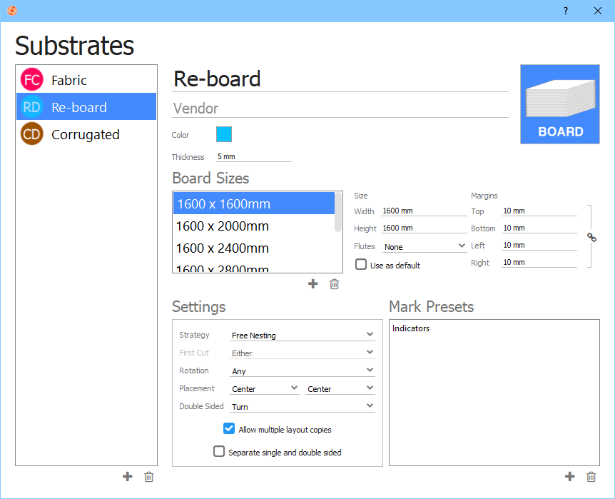
All the settings pertaining to the new or existing substrates are found on the right side of the dialog.
- Name – The name you want to give the substrate.
- Vendor – Optional vendor name of the substrate.
- Color – Click on the square color icon to change the display color used for the icon for this substrate. Color does not affect export in any way or appearance of the substrate in Layout View.
- Thickness – Substrate thickness. Thickness is included in Zund Cut Center (ZCC) cutting output to automatically match the substrate with the corresponding material in Zund Cut Center.
- Board Sizes / Roll Widths – A list of available board sizes or roll widths. To add a new board or roll, click the plus (plus) icon below the Board Sizes or Roll Widths list. Use the settings to the right of the list to configure the new or existing board/roll.
- Width – Width of the board or roll.
- Height – Height of the board.
- Flutes – Flutes (i.e. grain) direction for the board if any. Flutes are defined by which dimension is longer or shorter.
- Margins - The amount of spacing from the edges of the board or roll required. The Nesting Tool will not place any artwork item cut paths within this margin.
- Settings – Nesting related default settings for this substrate. See Section 3.5 for a description of each of these settings.
- Mark Presets – A list of pre-defined marks that will be automatically added to layouts in the Nesting Tool. For example, you might always want to use a specific set of camera marks or a barcode for the given substrate. See Section 4.3 for details on how to create mark presets.
To remove a substrate from the library, select the substrate in the list and click on the trash can icon below the list.
# Tool Types
Tool Types represent the various tools used by your cutting devices to cut, score, crease, etc. Each tool type defines tool properties as well as a list of mappings from artwork spot colors or PDF layer names to automatically map paths in your artwork to the correct tool type.
To add, edit, and remove tool types from your library, go to the Window menu and select 'Tool Types'. This will open the Tool Types dialog that displays a list of all current tool types and their properties.
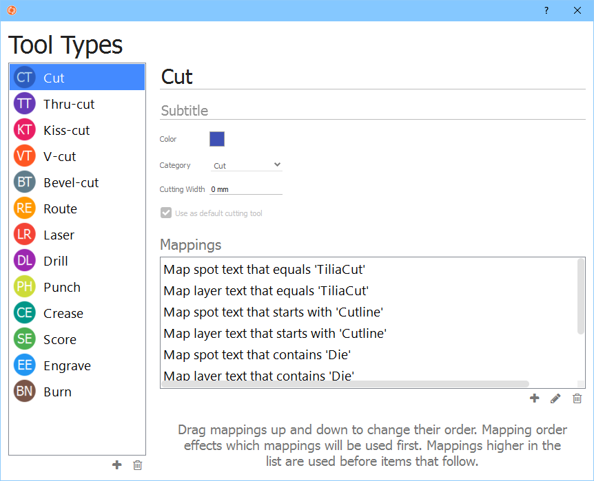
To add a new tool type, click on the plus (plus) icon below the tool type list on the left side of the dialog. This will insert a new tool type that you can edit on the right side of the dialog.
- Name – The name you want to give for the tool.
- Subtitle – Optional additional information you want to add for this tool.
- Color – Click on the square color icon to change the color used to draw tool paths of this type in Artwork View and Layout View as well as the icon for this tool type. Color does not affect export in any way.
- Category – The tool category this type belongs to: General, Cut, Crease, Annotation. Cut tool types are used to determine the shape of the artwork item and additional properties that can affect nesting.
- Cutting Width – (Cut category) The width of the cutting tool. This property can be used to define the spacing distance between items the Nesting Tool uses if the artwork item's spacing type is set to 'Tool'.
- Use as default cutting tool – (Cut category) Set this cutting tool as the default tool for cutting. When no paths in the artwork match any cut tool types, the rectangular dimensions of the artwork are used as the shape (Trimbox for PDF and AI formats) with the default cutting tool used as the tool type for the shape.
Next you will want to set up your mappings to automatically map paths in the artwork content to the correct tool type when new artwork is added to your jobs. To add a new mapping, click on the plus (plus) icon below the Mappings list. You will be presented with a mapping dialog.
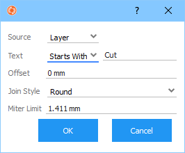
The mapping dialog contains the following settings:
- Source – The source of the mapping for PDF -based artwork formats: 'Spot' or 'Layer'.
- Text – The type of mapping rule you want to use: 'Equals', 'Starts With', or 'Contains' as well as the text to match. 'Equals' will match the given text exactly with spot or layer names in the artwork content, while 'Starts With' will match the given text with the beginning of the spot/layer name, and 'Contains' matches the text with any portion of the spot/layer name. All text matching is case insensitive.
- Offset – (Cut category) An optional offset to apply to the shape. Negative offset values will cause the shape to be reduced while positive values will increase the shape path. For example, this setting is useful to prevent a wider cutting tool from cutting into artwork content .
- Join Style – (Cut category) The style used to join path segments in the shape when an offset is applied. Options are 'Miter', 'Bevel', and 'Round'.
- Miter Limit – (Cut category) In cases where an offset is defined and the join style is 'Miter' the miter limit defines the distance beyond the end of the joined path segments where mitering is clipped to avoid long spikes on sharp corners. Once you have defined some mappings you can move them around in the list by dragging and dropping them with the mouse. The order of mappings can be important because once a stop color or layer name matches a tool type mapping, the other mappings below the matching one are not checked against that name. To ensure correct matching it is best to move mappings with more unique names higher in the mapping tables, with general catch-all names like 'cut' further down in the list.
Similarly, the tool types themselves can be ordered in the tool types list on the left side of the Tool Types dialog via drag and drop. The mappings are searched in order of the tool type from top to bottom of the list.
To edit a tool type, simply select it in the tool types list and edit its properties. To remove a tool type from the library, select the tool type in the list and click on the trash can icon below the list.
# Mark Presets
Mark Presets can help streamline your workflow by defining commonly needed marks once and reusing them. When paired with Substrates, marks are added automatically when layouts are created with the Nesting Tool, further reducing time and possible errors.
To add, edit, and remove mark presets from your library, go to the Window menu and select 'Mark Presets'. This will open the Mark Presets dialog that displays a list of all current mark presets and their properties.
Mark presets are separated into two categories: Artwork and Layout. To change between artwork and layout mark preset lists, go to the upper-left portion of the dialog about the mark preset list and click on the dropdown to select 'Artwork' or 'Layout'.
To add an artwork or layout mark preset, click on the plus (plus) icon below the mark presets list on the left side of the dialog. You will be presented with a menu with all supported mark types depending on whether you are adding Artwork or Layout mark presets.
# Artwork
- Barcode: Code 39, Code 128, QR Code
- Corner
- Fill
- Grommet
- Text
# Layout
- Barcode: Code 39, Code 128, QR Code
- Border
- Camera
- Corner
- Grommet
- Text
To edit a mark preset, simply select it in the mark presets list and edit its properties on the right side of the dialog. To remove a mark preset, select it in the mark presets list and click on the trash can icon below the list.
# Common mark properties
The following are a list of properties shared among two or more different mark types.
- Name – The mark preset name.
- Subtitle – Optional additional information you want to add for this mark preset.
- Color – Click on the square color icon to change the display color used for the icon for this mark preset. Color does not affect export in any way or appearance of the mark in Artwork View or Layout View.
- Smart Placement – (Barcode, Text) The placement rule to use when positioning the barcode or text mark into the artwork or layout. Use the 9-point selector to change which point on the mark (small square) is aligned to which point of the artwork or layout (large square). Use the 'X' and 'Y' values to define offsets from these anchor points with positive values moving the mark left and up respectively. You can also change the rotation of the mark by selecting the 'R' dropdown.

- Layer – Optional PDF layer name. When specified the marks will be placed in a PDF layer of the same name during printing and cutting export.
- Stroke – (Border, Camera, Corner, Grommet) The stroke color and thickness of the camera or grommet mark. To change color, click on the square color icon.
- Fill – (Border, Camera, Barcode, Text, Fill) The fill color of the mark content for Camera and Fill mark types and barcode and text color for Barcode and Text marks. To change color, click on the square color icon.
# Barcodes
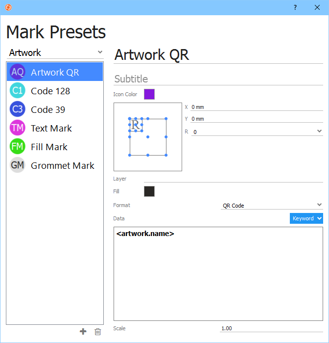
Barcodes are available in three standard formats: Code 39, Code 128, and QR Code. Barcodes can be applied to both artwork and layouts. All three formats have support for dynamic keywords for encoding job, layout, date, and artwork properties into barcodes automatically.

Use the common properties to define position and color via the common Smart Placement and Fill properties respectively. The following additional properties are available to control the size and content of barcodes.
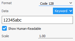
- Format – Barcode format: 'Code 39', 'Code 128', or 'QR Code'.
- Data – Click in the text area to enter the content you want the barcode to contain. To add a dynamic keyword, click on the 'Keyword' button and select the desired keyword from the menu that appears.
- Show Human-Readable – (Code 39, Code 128) If enabled, plain text of the data content will be included below the barcode.
- Scale – Scale factor to apply to barcode to increase or decrease its size.
# Border
Border marks are rectangular paths drawn at a given margin from the edge of the layout. Border marks are used for certain cutting devices such as Mimaki cutters.
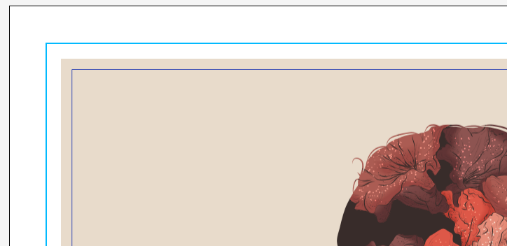
Border mark paths can be both stroked and filled. Stroke color and thickness and fill color are defined via the common Stroke and Fill properties. Additionally, the following margin settings control the dimensions and placement of the border mark.
- Top – Distance from the top edge of the sheet in the downward direction to draw the top edge of the border mark.
- Bottom – Distance from the bottom edge of the sheet in the upward direction to draw the bottom edge of the border mark.
- Left – Distance from the left edge of the sheet in the right direction to draw the left edge of the border mark.
- Right – Distance from the right edge of the sheet in the left direction to draw the right edge of the border mark.
# Camera
Camera marks are needed by camera-based cutting table registration systems. tilia Griffin camera marks are flexible and should support all major cutting table vendors.

Camera marks support both circular and cross shapes. Circular shapes can be both stroked and filled. There is also an intelligent auto distribute feature with various options to automatically place camera marks near artwork items throughout the layout.
Below is a list of camera mark properties in addition to the common properties described in the previous section.
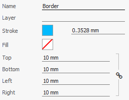
- Shape Type – Circle, square, or cross camera mark shape type.
- Size – The size of each camera mark instance.
- Offset – The offset to place camera marks from the shape of artwork items.
- Auto Distribute – Whether to automatically place camera marks throughout the layout. When disabled, only corner camera marks are placed.
- Mode – Distribute mode to use when auto distributing: Spacing or Quantity. Spacing mode will distribute marks throughout the layout at certain spacing interval while Quantity will place a specific number of marks in the layout.
- Min Spacing – The minimum distance allowed between camera marks when using Spacing auto distribute mode. Increasing this number will reduce the number of camera marks placed in the layout.
- Quantity – The specific number of marks to add when using Quantity auto distribute mode. This is useful in cases where you know how many extra marks you want Griffin to automatically add regardless of the layout size. Note: It is not guaranteed that the quantity target can be met if the amount of empty space in the layout is limited.
- Add Corners – Whether to place camera marks in the four corners of the layout.
- Double Corner – Whether to include a second corner mark in the lower-right corner of the layout. If enabled, the second corner mark placed to the left of the right corner camera mark by the specified distance.
- Margins – Use 'Layout Margins' to ensure camera marks are not placed outside the allowed content region of the layout or use 'Custom Margins' to define custom distances from each sheet edge where camera marks can be placed.
- Mirror to Back – When enabled, camera marks are automatically mirrored to the back side of the layout. This is useful for cases when the layout will be getting cut face down on the cutting table.
# Corner
Corner marks are placed at the four corners of the given artwork or layout. Corner marks are used by certain cutting devices such as Mimaki cutters.
Corner marks come in two flavors: Type 1 and Type 2. Both types are simple "L" shaped stroked marks, with Type 1 corner marks facing towards the artwork or layout and Type 2 facing outwards.
- Type 1:

- Type 2:

Use the Stroke common property to define stroke color and thickness. In addition, you can select the type as described above and the following additional properties.
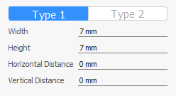
- Width – Width of each corner mark, i.e. the distance from the corners to extend the horizontal lines.
- Height – Height of each corner mark, i.e. the distance from the corners to extend the vertical lines.
- Horizontal Distance – Optional distance to offset the corner mark in the horizontal direction. Positive values will move the corner point away from the artwork or layout while negative values will move the corner point inside the artwork or layout.
- Vertical Distance – Optional distance to offset the corner mark in the vertical direction. Like Horizontal Distance, positive values will move the corner point away while negative values with move the corner point inside the artwork or layout.
# Fill
Fill marks are used in artwork to place ink below the shape of the artwork item. To configure a fill mark, set the common Fill color property as well as the Margin offset value if you want the fill mark to extend beyond the shape of the artwork item.
# Grommet
Grommet marks are placed evenly across edges of artwork or the layout. Often, they are used to denote grommet or punch hole locations for hanging pieces. Grommets can be crosshair, circle, or cross shaped.

Use the Stroke common property to define stroke color and thickness. In addition, there are a number of properties specific to grommet marks.
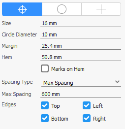
- Shape Type – Choose between crosshair, circle, and cross shapes.
- Size – The size of each grommet mark instance.
- Circle Diameter – (Crosshair shape) The diameter of the inner circle in crosshair shaped grommet marks.
- Margin – The margin offset to place grommet marks from the bounds of the artwork or layout.
- Hem – The width of the hem.
- Marks on hem – If enabled, grommet marks will be mirrored onto the hem so they line up when the edges are folded.
- Spacing Type – This property controls how grommet marks are distributed across the edges. 'Max Spacing' will evenly place marks placing them as far apart as possible up to the max spacing distance. 'Quantity' will place exactly number of marks defined in the horizontal and vertical quantity properties.
- Edges – Include or exclude specific edges.
# Text
Text marks can be used in both artwork and layouts, and can contain static text, dynamic text keywords or a combination of both.

Text color is controlled by the common Fill property. Text marks also include the following properties that allow you to control text content and appearance.
- Font – Select the font you want to use from the font dropdown.
- Font Size – Select the font size you want to you from the size dropdown.

- Font Style – Choose what font style you want the text mark to appear as. Options vary depending on the font you are using, but most fonts support 'Normal', 'Normal Italic', 'Bold', and 'Bold Italic' styles.
- Content – Click in the text area to enter the content you want for the text mark. To add a dynamic keyword, click on the 'Keyword' button and select the desired keyword from the menu that appears.
# Tiling Presets
Tiling presets are pre-defined tiling settings that you can quickly select when using the tilia Griffin tiling feature. If you are creating tiles using the same or similar settings on multiple occasions, then defining presets can save you time and reduce errors.
To add, edit, and remove tiling presets from your library, go to the Window menu and select 'Tiling Presets'. This will open the Tiling Presets dialog that displays a list of all current tiling presets and their properties.