# Creating a Griffin Job
When Griffin first launches, the Start Window will appear, allowing you to create a new job, open a job from the "Open Job" dialog, or choose from a list of recently open files.
Click "New…" to create a new Griffin job. You will see a new Job Window appear with an empty artwork list.
Note: These same options are also available from the File menu at any time.
# Set job properties
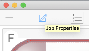
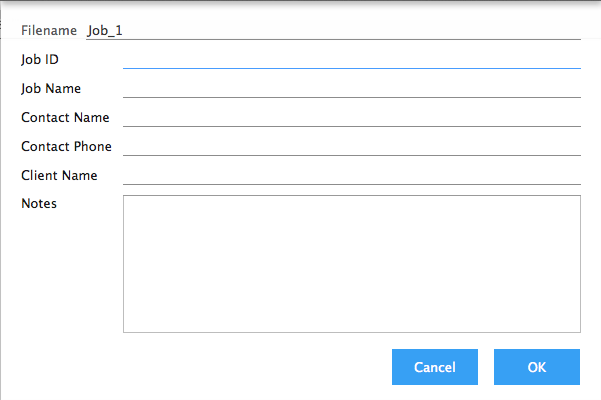
Now that we have a new job we can optionally set job properties. Job properties (Client Name, Job ID, Contact Name, etc.) are useful for recording information about the current job and can be used in dynamic text and barcode marks. Click on the Job Properties button in the Toolbar to edit these properties.
Changes are accepted by clicking the 'OK' button in the lower-right corner of the dialog.
# Add artwork
tilia Griffin supports PDF and PDF-based Illustrator (AI) formats, as well as TIFF, BMP, PNG, JPG, and GIF image artwork formats.
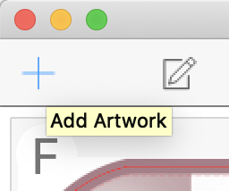
To add new artwork to your job, click the Add Artwork button in the Toolbar while in Artwork list view.
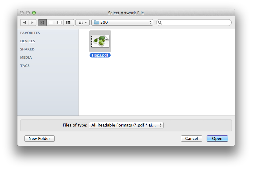
A Select Artwork File dialog will appear. Choose the artwork file you would like to add and click the 'OK' button in the lower-right corner of the dialog.
Alternatively, you can select "Import Artwork…" from the File menu to add artwork to your job or drag files directly into your Job Window from Finder (OS X) or Explorer (Windows).
Maximum Number of Products
Griffin supports up to 100 products in a job
# Edit artwork properties
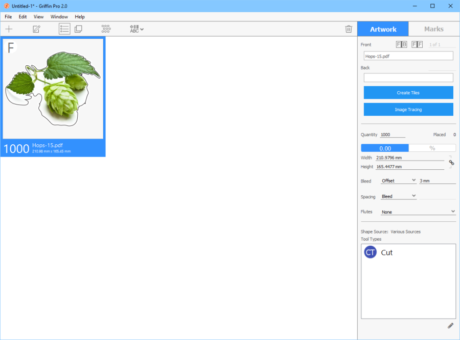
In Artwork List, select your artwork item. On the right side in the Sidebar you will see "Artwork" and "Marks" tabs. Go to the Artwork tab and click on the Quantity edit box to change the quantity needed for this artwork.
You will notice that the quantity is updated instantly. In general, property values are applied automatically when changes are made.
Note: If you select multiple artwork items in the Artwork List, changing property values in the Sidebar will update all selected items simultaneously.
There are several other artwork properties which you are free to change at any time:
- Front – The artwork file and page number to use for the front side content of this artwork item.
- Back – The artwork file and page number to use for the front side content of this artwork item.
- F | B Button – Mirror Front to Back: When clicked, a mirrored copy of the front side artwork content will be used on the back side of the artwork item.
- F | F Button – Front to Back: When clicked, the front side artwork content will be used on the back side of the artwork item as well.
- Create Tiles Button – Create tiles from the selected artwork. When clicked, Tiling View will appear allowing you to change tiling settings with a live preview of the tiles. See Section 7 for a detailed description of tiling.
- Image Tracing Button – Generate tool paths around image contours automatically. When clicked, Image Tracing View will appear allowing you to fine-tune settings and preview the generated shape path. See Section 8 for a detailed description of this image tracing.
- Quantity – Number of artwork items needed in this job, used by the Nesting Tool to ensure your orders are all placed onto layouts.
- Placed – (Read only) The current total number of placed copies of this artwork item across all layouts in this job.
- Width / Height – The dimensions of the artwork item. Both width and height can be edited which will cause the artwork item to be scaled automatically. When the percentage sign is selected (%) the dimensions are determined based on the percentage of original artwork content on the front side of the artwork item.
- Bleed – The type of bleed mask to apply to the artwork item: Offset or None. When Offset is used, you can change the bleed mask distance from the shape of the artwork item in the field to the right of the bleed type.
- Spacing – The type of spacing the Nesting Tool will use to determine how close to place artwork items to together when generating layouts: Tool, Bleed, or Offset. Tool spacing will use the Cutting Width of the tool type of the cut paths in the artwork item to determine the necessary spacing. Bleed spacing uses the bleed masks in the artwork item for spacing, ensuring bleed masks do not overlap. When Offset is used, you can change the spacing distance from the shape of the artwork item in the field to the right of the spacing type.
- Flutes – The required flute direction for this artwork item: Horizontal, Vertical, or None.
- Shape Source – (Read only) A description of where the shape of the artwork item came from.
- Tool Types – A list of all the tool types in selected artwork item(s). Click the edit icon below the list to change tool type mappings for all selected artwork items. See Section 4.2 to learn how tool type mappings are defined in tilia Griffin.
# Create layouts
Now that we have our artwork set up, we are ready to generate some layouts. First, click on the Nesting button in the Toolbar while you are viewing the Artwork List or Layout List.
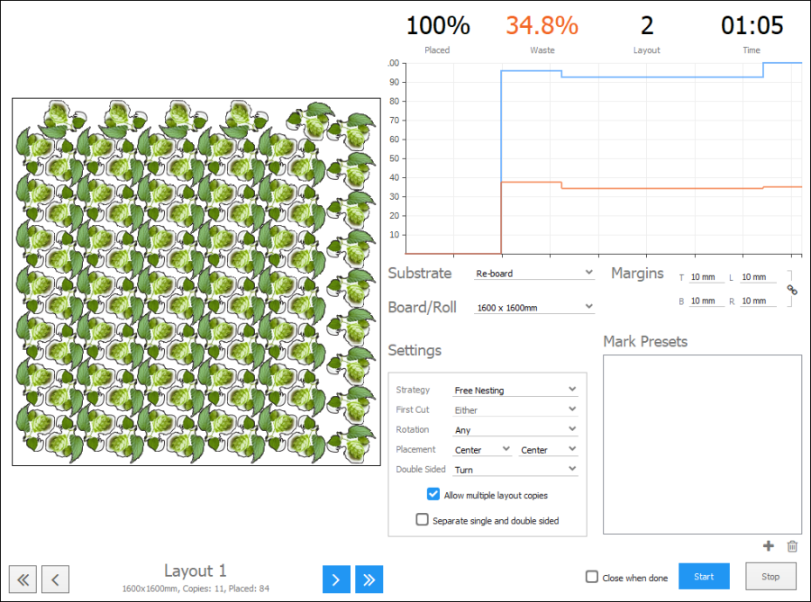
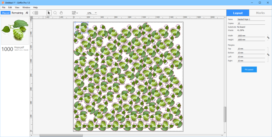
This will open the Nesting Tool. Next select the substrate and board or roll you wish to use and click 'Start' to begin generating layouts. Once the Nesting Tool is done or you are satisfied with the current layouts, click outside of the Nesting Tool or on the 'X' icon in the upper-right corner of the Job Window to exit. In the example below, we have selected the "Re-Board" substrate with a board size of 1600 x 1600 mm.
You will notice additional options in the Nesting Tool. You can set default values for these options in the substrate. See Section 4.1 for more details on how to define substrates. You can also change these options directly here in the Nesting Tool when the tool is not running.
Below is a description of all options in the Nesting Tool:
- Substrate – The substrate to use.
- Board / Roll – The board or roll size from the substrate to use.
- Margins – The amount of empty space needed from the edges of the board or roll. The Nesting Tool will not place any artwork item cut paths within these margins.
Note
Artwork bleed can go outside the margins - the margins only account for area where cut paths will not be placed.
- Strategy – The type of layout to generate based on your cutting requirements.
- "Free Nesting" enables the Nesting Tool to nest artwork items in any way to produce the tightest packed layouts.
- "Grid Nesting" ensures artwork items are placed in nested, repeating grid patterns.
- "Guillotine" produces layouts that can be cut out by a guillotine cutting device.
- First Cut – For Guillotine layouts, set whether the first cut needs to be horizontal, vertical, or either.
- Rotation – Allowed rotation of artwork items being placed: Orthogonal, Any, or None.
- Placement - The placement of artwork items relative to the board or roll.
- Roll Cut-off – Minimum and maximum lengths allowed for rolls.
- Double Sided - Whether double sided handling is turn or tumble based. When Nesting Tool places double-sided artwork items on a layout it will automatically mirror the layout on the back side based on this setting to ensure alignment between front and back.
- Allow multiple layout copies – Whether to allow multiple layout copies. When artwork item quantities are two or more times higher than the amounts placed on a layout, the Nesting Tool will increase the number of copies of the given layout instead of generating new layouts to fulfill those artwork items.
- Separate single and double sided – When enabled, single- and double-sided artwork items in the job are always placed into separate layouts.
- Mark Presets – A list of pre-defined marks to automatically add to generated layouts. See Section 4.3 for details on how to create mark presets.
# Edit layout properties
After running the Nesting Tool you will see the generated layouts in the Layout List. You can now edit properties on each layout if needed. Click on Layout 1 in the list and go to the Sidebar on the right side of the Job Window. There you will see 'Layout' and 'Marks' tabs. Make sure you are on the Layout tab and change the Name property.
Note: As with artwork properties, you can select multiple layouts to edit them at the same time.

Below is a full list of layout properties:
Name – The name of the layout. Layout name can be used in dynamic text/barcode marks.
- Copies – The number of copies of this layout to produce.
- Substrate – (Read only) The substrate used in this layout.
- Waste – (Read only) The percentage of the layout that is unused, e.g. throwaway material.
- Width – The width of the layout. Editing this property will adjust the layout's width.
- Height – The height of the layout. Editing this property will adjust the layout's height.
- Margins – The amount of space from the edges of the layout where artwork items are not to be placed.
# Make layout adjustments
The Nesting Tool is designed to produce efficient, print-ready layouts, but you can also go into individual layouts at any point and adjust artwork and mark item positions manually.
In Layout List double click on the first layout to enter Layout View. In Layout View you can select one or more artwork items and move them with the mouse or arrow keys. You can also change layout properties for this layout as you did in the last section and add, edit, or remove marks from the layout.
# Add camera marks to your layouts
Marks can be added to the artwork or to the layout at any time by clicking the Marks icon in the Toolbar in either list or view modes and choosing from the list of available mark types.
Alternatively, you can go to the Marks tab in the Sidebar and click the plus sign (plus) under the marks table to add a pre-defined mark preset. See Section 4.3 for details on how to create mark presets.
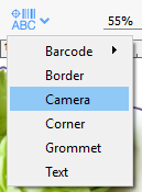
To add camera marks to a layout, select one or more layouts in the Layout List and click the Marks button in the Toolbar, selecting the "Camera" menu option.
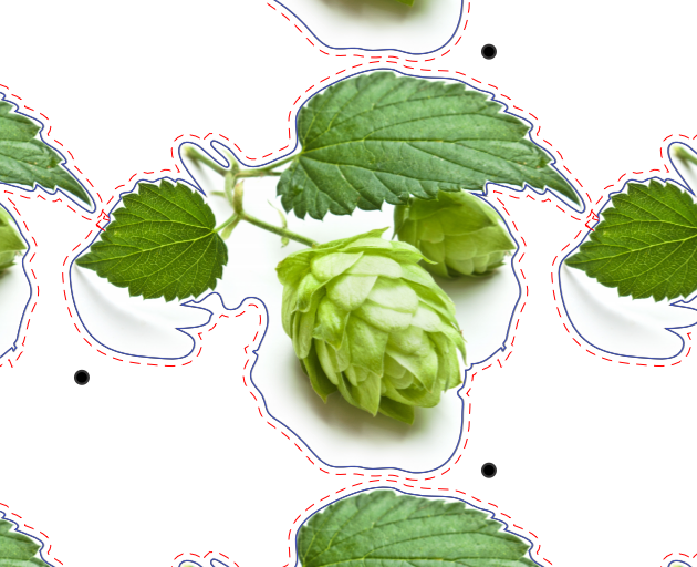
This will add camera marks to the selected layouts using default values.
Next, go to the 'Marks' tab of the Sidebar on the right side of the Job Window to make live edits to your camera marks.
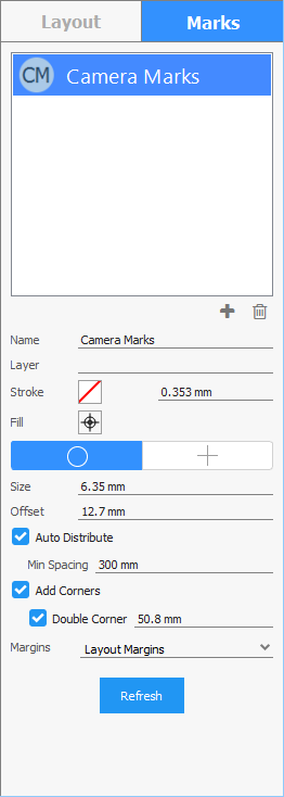
See Section 4.3.4 for details on how to configure camera marks.
# Add barcodes to your artwork
Go back to Artwork List and either select the artwork item or double click to enter Artwork View.
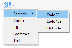
Next, click the Marks button in the Toolbar and select 'Barcode' -> 'Code 39'.
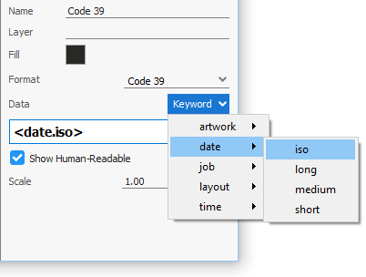
You have now added a Code 39 barcode to the artwork item with default properties. Go to the 'Marks' tab of the Sidebar, select Code 39 from the marks table to edit the mark's properties. The barcode data can be plain text and/or dynamic keywords that are automatically updated when their values change in the job.
We will use a dynamic keyword to encode the current date in ISO date format. To do so, click on the 'Keyword' button in the Sidebar and select 'date' -> 'iso' from the dropdown menu.
Now that we have our barcode data set, we just need to adjust the barcode position within the artwork item. To do so, enter Artwork View if you haven't done so already by double-clicking on the item in the Artwork List. In Artwork View you can select the barcode with your mouse and drag it to the desired location.
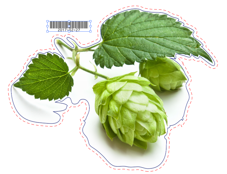
Alternatively, you can specify an exact position and rotation of the barcode in the Sidebar.
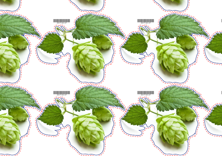
Mark contents and position are always synchronized across all instances of the artwork item in the job.
Note: You can also apply marks from your Mark Presets library which allows you to set the desired property values once and reuse them. To apply an existing mark preset, go to the 'Marks' tab in the Sidebar and click on the plus (plus) icon below the live of marks in the artwork or layout where you can select one or more mark presets from the dialog. See Section 4.3 for more information about how to create and manage your mark presets.
# Export for Printing
Once the layout is complete and all marks have been added, the job layouts can be exported for printing. To export an imposed printing PDF, go to the File menu and select 'Export for Printing…'. This will open the export dialog.
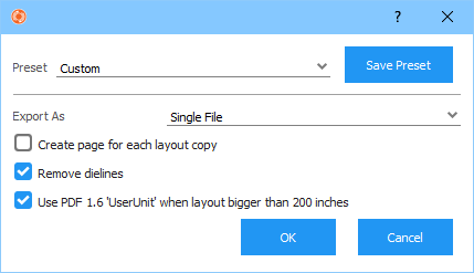
Choose a preset or select the type of export. Export options are: Export As
- Single File – All sides of every layout are contained in a single multi-page PDF. One File per Layout – One PDF file is created for each layout. If the layout is double sided, the PDF for that layout will be two pages with the first and second pages containing the front and back sides of the layout respectively.
- One File per Side – One PDF file is created for each layout side.
- Create page for each layout copy - In addition to export options you also have the option to create a separate PDF file or page for each copy of the layout that is needed to fulfill quantities by enabling the Create page for each layout copy checkbox. For example, if a layout contains 10 instances of an artwork item that has a quantity of 100, the number of copies of that layout is 10. If Create page for each layout copy is not enabled, the layout sides are exported once. However, if enabled, each side of the layout will be exported 10 times, one time for each of the 10 layout copies.
- Remove dielines - When enabled, original dieline paths are removed from the artwork content during export. Note: Currently tilia Griffin can only remove dielines defined using spot colors in the PDF or AI file, not PDF layer-based dielines.
- Use PDF 1.6 'UserUnit' when layout bigger than 200 inches - Use this option if you are working with layouts with dimensions over 200 inches (roughly 5 meters) and your RIP supports the PDF 1.6 'UserUnit' field to address size limitations in the PDF specification. Once you are ready to export, click 'OK' and a Save File dialog will open. Select a file name and folder to save the PDF. You may also wish to save the settings as a new preset by clicking on the 'Save Preset' button.
# Export for Cutting
Now you are ready to export for cutting. Select "Export for Cutting…" from the File menu to open the export dialog. The first step is to choose the cutting export format. Tilia Griffin supports three different cutting formats: PDF, DXF, and Zund Cut Center (ZCC). Next you can configure common and format-specific settings to generate the right cutting data for your devices. Click 'OK' when you are ready and a Save File dialog will open where you can select a file name and folder to save the cutting file(s). Like with Export for Printing, you can save your current settings as a new preset by clicking on the 'Save Preset' button to use again in the future.
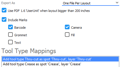
PDF cutting files are compatible with several industry standard cutting tables. Options include: Export As
- Single File – All layouts are contained in a single multi-page PDF.
- One File per Layout – One PDF file is created for each layout.
- Use PDF 1.6 'UserUnit' when layout bigger than 200 inches - Use this option if you are working with layouts with dimensions over 200 inches (roughly 5 meters) and your cutting device supports the PDF 1.6 'UserUnit' field to address size limitations in the PDF specification.
- Include Marks – Which marks if any to include in cutting output.
- Tool Type Mappings – Table of mappings from tool types to colors and PDF layers expected by your cutting device. Click on the icons below the table to add, edit, or delete mappings.
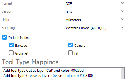
# DXF
DXF (Drawing Exchange Format) is an open standard CAD format used by several hardware manufacturers. Options include:
- Version – DXF version to use: R13 or 2007.
- Units – Which units to use in DXF path and dimensions data.
- Encoding – For the older R13 DXF version you need to specify the character encoding to use during export via the Encoding setting. DXF version 2007 and above always uses UTF-8 encoding which supports all Unicode characters.
- Include Marks – Which marks if any to include in cutting output. Text marks are not supported in DXF
- Tool Type Mappings – Table of mappings from tool types to DXF layer names and DXF colors expected by your cutting device. Click on the icons below the table to add, edit, or delete mappings.
# Zund Cut Center (ZCC)
ZCC cutting export format for tight integration with Zund Cut Center for customers using Zund cutting tables. Griffin records various useful information into the ZCC cutting file that is not included in generic cutting PDFs:
- Name of the substrate
- Number of required copies of the layout
- Flutes direction
- The job name which can be defined using dynamic keywords
This metadata can be leveraged in Zund Cut Center to choose the correct blades and speeds for the given cutting table and to report useful information to the operator.
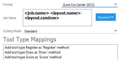
ZCC export options include:
- Job Name – The Job Name field in Zund Cut Center. You can use dynamic keywords to record properties from the current job or layout along with date and time.
- Cutting Mode – The cutting mode to use in Zund Cut Center: Standard, Quality, or Speed.
- Tool Type Mappings – Table of mappings from tool types to Zund methods. Mappings are read-only to ensure correct tool mappings are used.
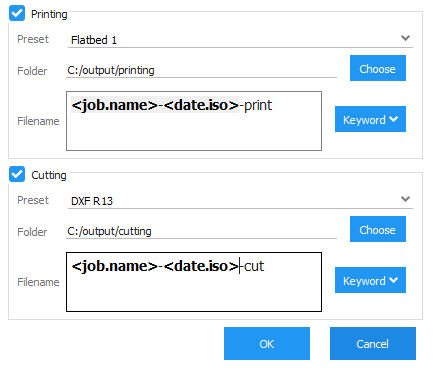
# Export Multiple
You can export both printing and cutting files in a single shot by using the Export Multiple feature.
Go to the File menu and select "Export Multiple…". The Export Multiple dialog will open. This dialog is divided into Printing and Cutting sections which can be setup independently. In each section has the following settings:
- Preset – The pre-defined printing or cutting preset you want to use during export
- Folder – Output folder to save exported files to. This can be a hot folder for your RIP or cutting table software for example.
- Filename – The filename of the exported files. You can use dynamic keywords to automatically generate filenames containing job properties, layout name or ID, current date/time and more.
These settings can be saved as an Export Multiple preset as well, allowing you to quickly select all desired export settings again in the future.