# Marks
There are 18 different types of marks available within Phoenix, plus an optional Script Mark available with the Scripting module that allows you to create any mark you can think of.
To create a new mark (or modify an existing one), navigate to the Marks panel, and select "New Mark..." from the dropdown in the top left of the panel.
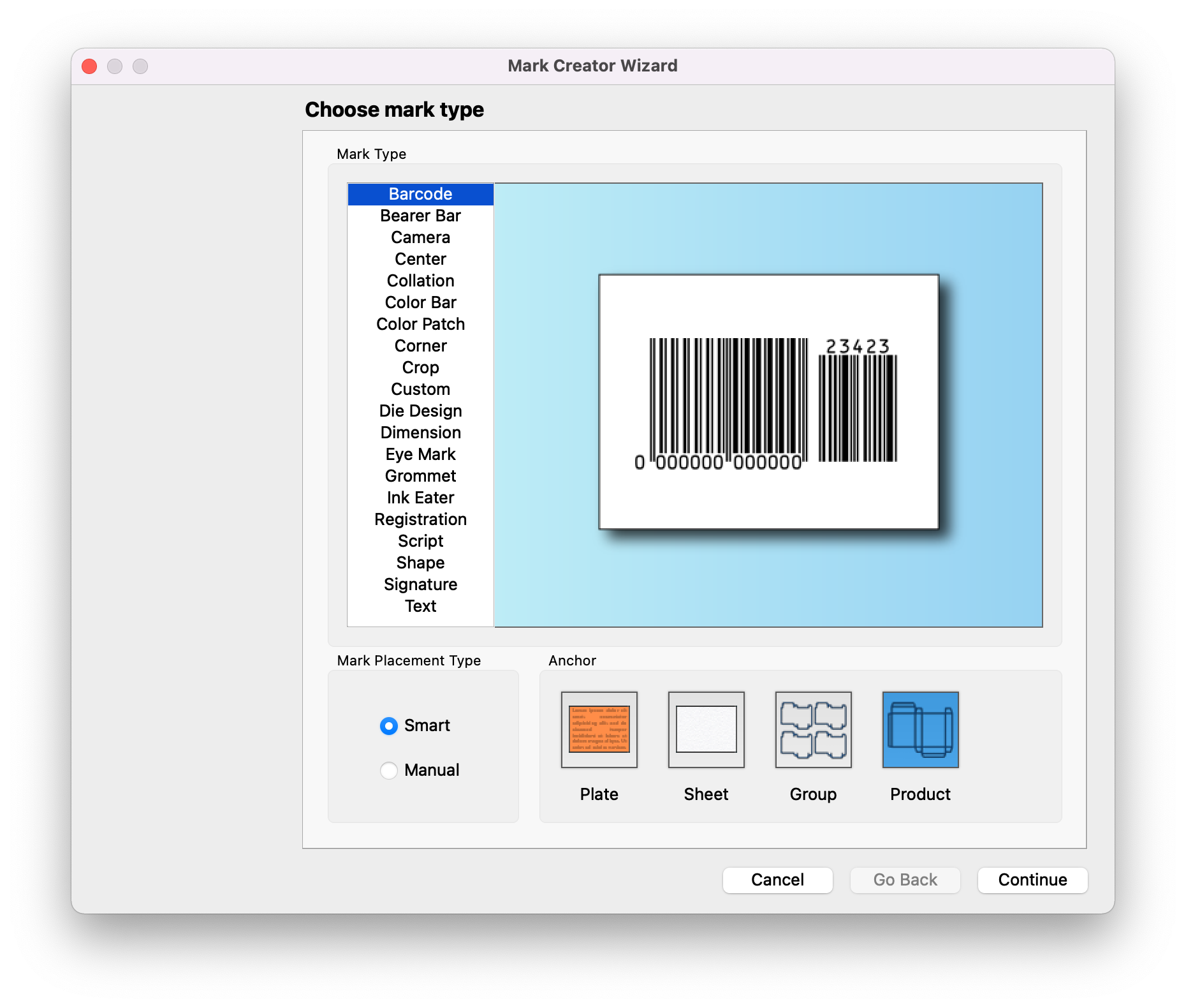
This will open the Mark Creator Wizard, which will allow you to select the type of mark, as well as how it will be placed. The screens in the Mark Creator Wizard will vary based on the options selected. After the settings are chosen for each screen, use the navigation buttons at the bottom right of the window to either Continue, Go Back, Cancel, or complete the wizard by clicking "Done."
| Field | Description |
|---|---|
| Mark Type | Select your mark type. As you click on each type, the preview will change to reflect the mark you have selected |
| Placement Type | Choose whether to place the mark manually, or using Smart placement. Smart placement will attach the mark to an anchor, as selected below |
| Anchor | If Smart placement is selected, choose to anchor the mark to the Plate, the Sheet, a Group, or an individual Product. Exact placement will be determined in the final step of the Mark Creator Wizard. |
# Print Settings
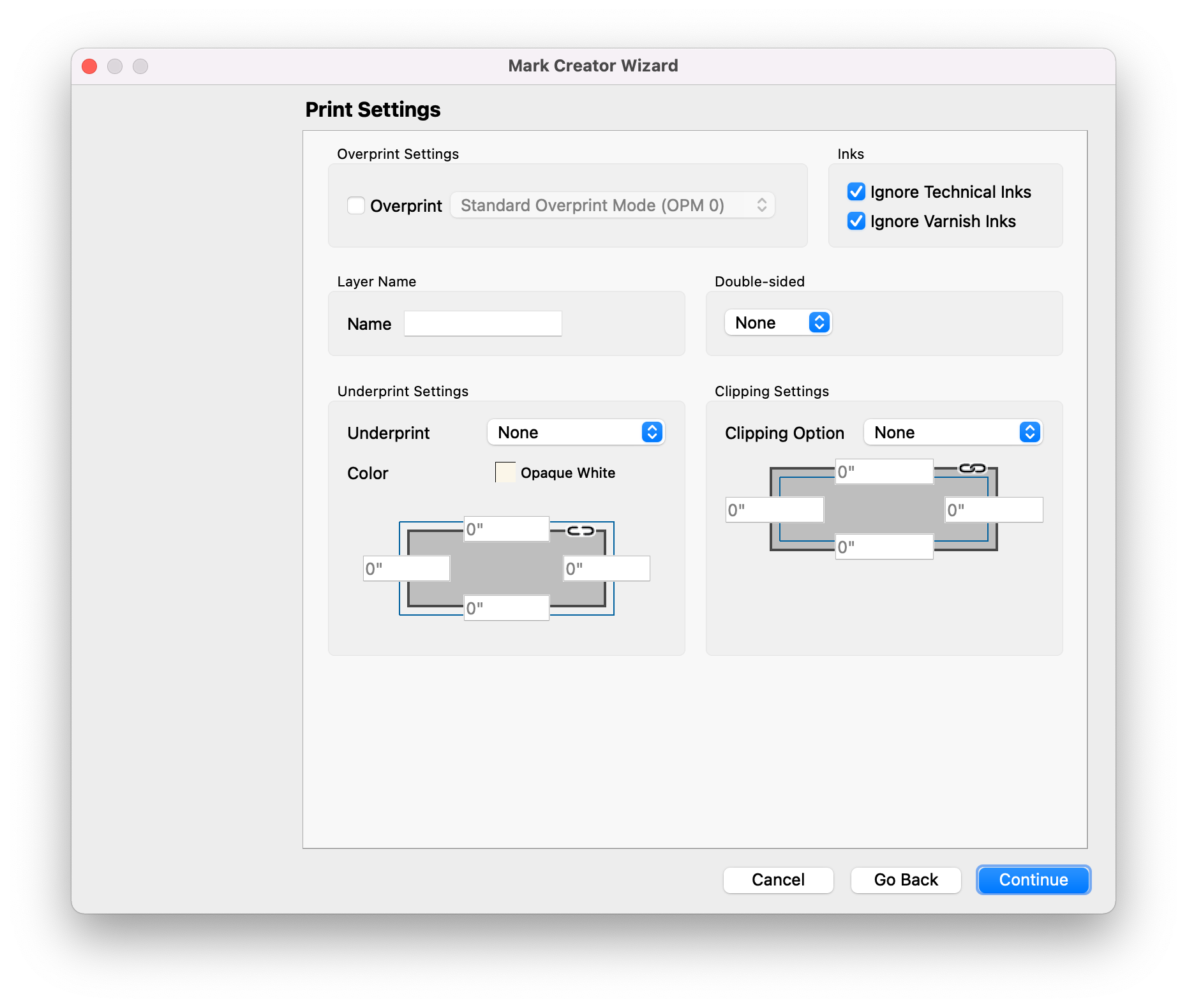
Every mark has the same print settings options. Here, you can define how the object will print, including overprint, whether to ignore ink types, the layer name, underprint, and clipping
| Field | Description |
|---|---|
| Overprint | Option to enable overprint for the mark, and if so, which overprint Modeto use. |
| Ignore Technical Inks | Option to ignore technical and/or varnish inks in the Colorof the mark |
| Layer Name | This field allows you to specify which output layer the mark is placed on. If a value is set here, a layer will be created with the layer name specified. If no value is set, no layer is created for the mark, and it is placed with the rest of the layout artwork. |
| Double-sided | Optionally mirror the mark to the back side if the item is double-sided |
| Underprint | Option to add underprint, in the specified color, to the mark. |
| Clipping Option | Option available in some mark types to clip the mark to the anchor bounds. You can specify a margin inside the bounds to clip the mark so that it doesn't extend past the bounds. |
# Mark Placement
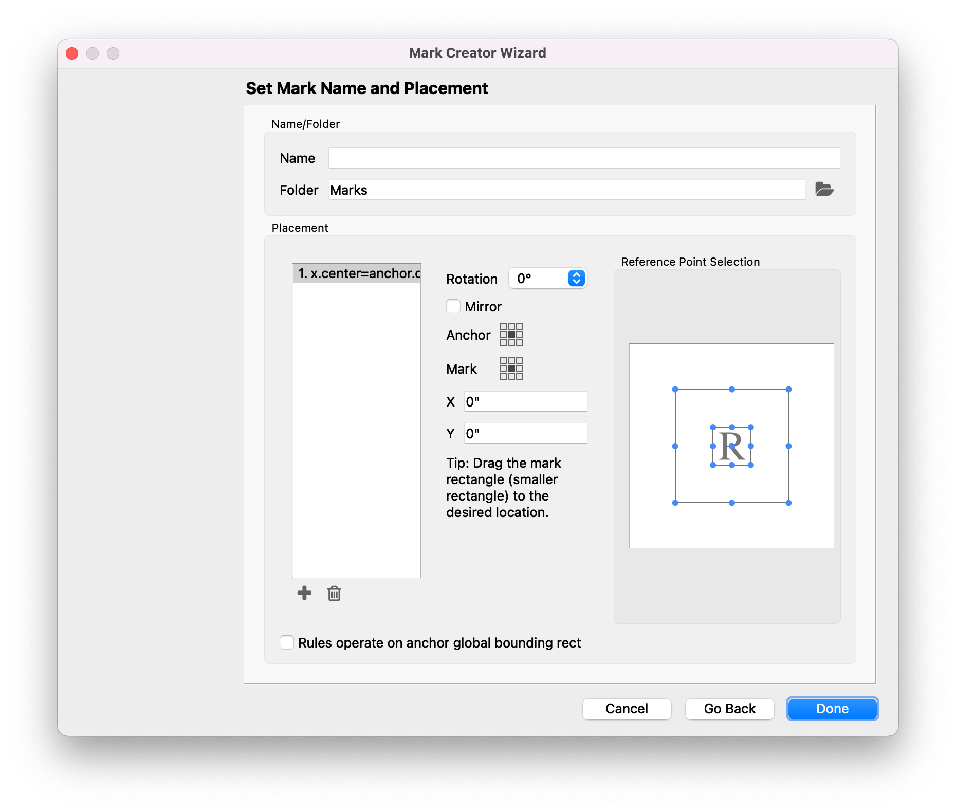
When Smart Mark Placement Type is chosen, the Mark Placement screen will be available. This screen allows you to define how the mark will be placed relative to the anchor.
| Field | Description |
|---|---|
| Name | Give the mark a unique name |
| Folder | Optionally, select a folder within the Marks panel for organization |
| Placement Instance | By default, one instance of the mark is created. You can add additional instances with unique placement for each by clicking the Add button at the bottom, or remove instances, by selecting the instance you want to remove, and clicking the remove button. |
| Rotation | Rotate the selected mark instance in 90° increments |
| Mirror | Mirror mark horizontally. Useful for backside printing on transparent materials |
| Anchor | Select from the 9-point grid where the mark should be placed relative to the anchor. This grid represents the anchor. For instance, if you want the center of the mark to be placed on the center of the anchor, select the middle of this 9-point grid and the middle of the Mark 9-point grid. If you want the center of the mark to be anchored to the bottom left of the anchor, select the bottom left of this 9-point grid and the middle of the Mark 9-point grid. |
| Mark | Select from the 9-point grid where the mark should be placed relative to the anchor. This grid represents the mark. For instance, if you want the top right of the mark to be placed on the top left of the anchor (so that the top of the mark is aligned to the top of the anchor, and the mark sits to the left of the anchor), select the top right of this 9-point grid and the top left of the anchor 9-point grid. If you want the bottom left of the mark to be anchored to the bottom left of the anchor, select the bottom left of this 9-point grid and the bottom left of the Mark 9-point grid. |
| X and Y | Define how the mark should be transformed horizontally and vertically from the anchor point. A positive X value moves the mark to the right, and a positive Y value moves the mark up. |
| Reference Point Selection | This graphic provides an alternate representation of the Anchor and Mark selections. As you make changes to the Anchor, Mark, or the Reference Point Selection, the others will update to reflect the change. |
| Rules operate on anchor global bounding rect | Define position and rotation based on the global bounding rectangle of the anchor item. |
# Barcode
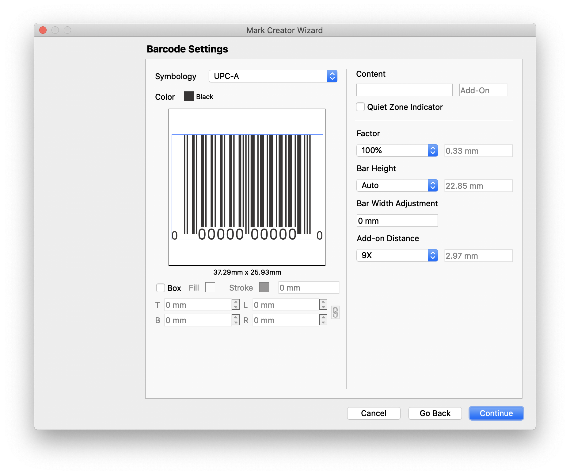
Barcode marks allow you create one of 14 common barcode types. The barcode parameters will vary based on the symbology chosen, but many of the parameters are common to all barcode types.
| Field | Description |
|---|---|
| Symbology | The type of barcode desired. Supported Barcode types are Aztec, Codabar, Code 39, Code 128, Data Matrix, EAN-8, EAN-13, Interleaved 2 of 5, One-track Pharmacode, Two-track Pharmacode, POSTNET, QR Code, UPC-A, and UPC-E |
| Color | Define the Color of the barcode |
| Box | Option to create a box around the barcode. You can define the fill and stroke colors, stroke size, as well as extra margin around the Top, Bottom, Left, and Right of the amrk. |
| Content | The data to be encoded in the barcode. This field is dynamic keyword enabled, meaning that you can have the content automatically populated with data from the project. To use a dynamic keyword, enter < in the content field, and either type or click the dynamic keyword you want to use. For more on keywords, check out Dynamic Keywords. For applicable barcode types, an Add-On content field is available. |
| Quiet Zone Indicator | A quiet zone adds a margin around the outside of the mark to make scanning easier. |
| Factor | Scales the barcode by the specified factor |
| Bar Height | Defines the height of each bar |
| Bar Width Adjustment | Adjust the width of the bar to account for the printing process |
| Add-on Distance | If Add-On content is sepcified, this field defines how far the add on is away from the primary barcode content. |
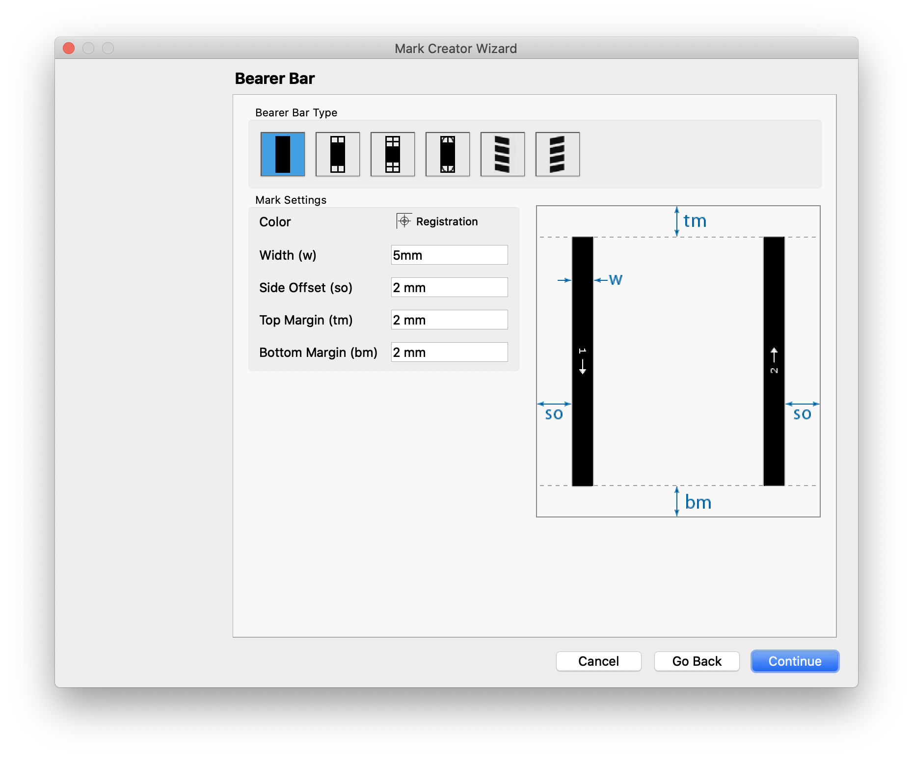
# Bearer Bar
Bearer Bars are two solid bars added to either side of a layout that run the length of the layout, generally for flexo printing.
| Field | Description |
|---|---|
| Bearer Bar Type | Select the type of bar you prefer. As you select each option, the preview will update to show you how they will appear. The graphic representatin includes callouts with arrows and letters that correspond to each setting below. |
| Color | Define the Colorof the bar. By default the Coloris registration. |
| Width | Set the width of each bar. |
| Side Offset | The offset distance from the outer vertical edge (left and right) of the layout to where the bar starts. |
| Top Margin | The margin distance from the top of the layout to where the bar starts. |
| Bottom Margin | The margin distance from the bottom of the layout to where the bar starts. |
| Thickness | For certain Bearer Bar Types, thickness refers to the stroke width of the lines that appear in the bearer bar. |
| Repeats | For certain Bearer Bar Types, the number of repeated sections in each bar |
| Step Height | For certain Bearer Bar Types, the step distance between bearer bar patches |
| Patch Height | For certain Bearer Bar Types, the height of each bearer bar patch |
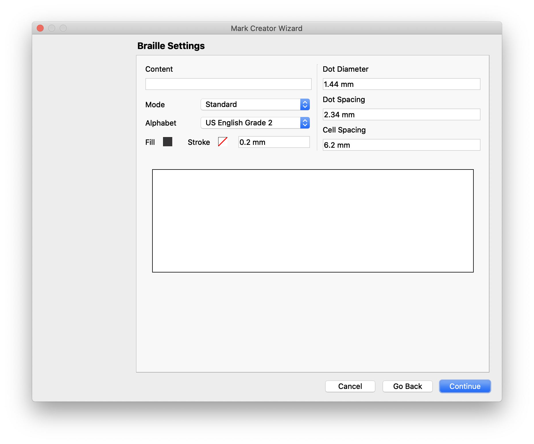
# Braille
With the optional Braille module, this marks allows you to dynamically create braille.
| Field | Description |
|---|---|
| Content | The data to be represented with brailled. This field is dynamic keyword enabled, meaning that you can have the content automatically populated with data from the project. To use a dynamic keyword, enter < in the content field, and either type or click the dynamic keyword you want to use. For more on keywords, check out Dynamic Keywords. |
| Mode | Choose between Standard braille or ADA Compliant braille. |
| Alphabet | Select which braille alphabet to use |
| Color | Define the Colorof the braille mark |
| Dot Diameter | Set the diameter of each braille dot |
| Dot Spacing | Set the spacing between dots within a cell |
| Cell Spacing | Set the spacing between each cell |
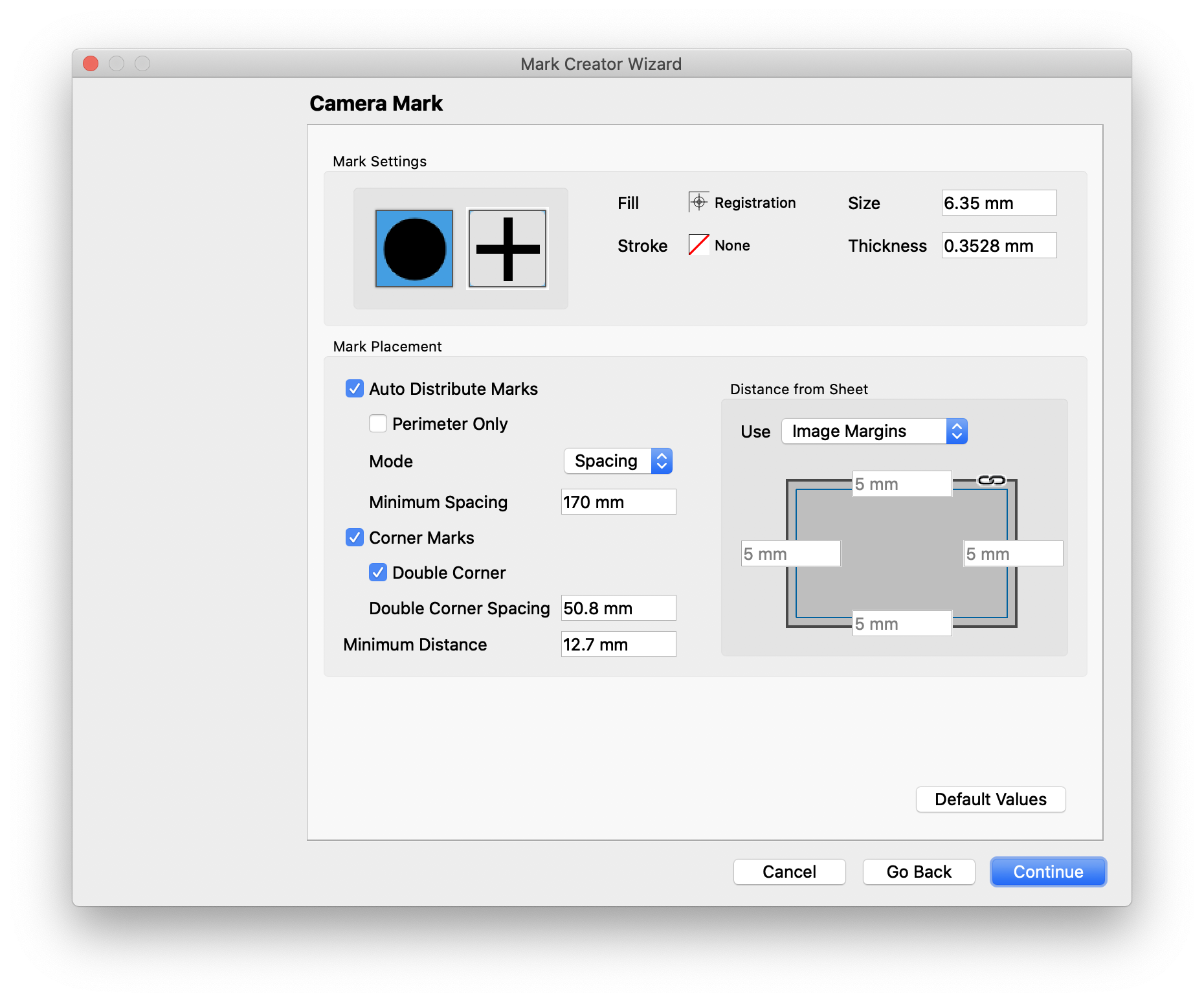
# Camera
Camera marks are designed for items that need to be cut out on a table cutter equipped with a camera. These marks enable a camera on the table to align with the printed piece and ensure the machine is making accurate cuts.
| Field | Description |
|---|---|
| Mark Shape | Choose between a circle or cross |
| Color | Define the fill and stroke of the mark |
| Size | Set the Sizeof the mark and thickness of stroke, if applicable |
| Auto Distribute Marks | Automatically place marks along the length of the layout |
| Perimeter Only | If auto distributing marks, only place them along the outside of the layout |
| Mode | Choose between Quantity, where a specific number of marks are distributed, or spacing, which sets a minimum spacing between marks and lets Phoenix determine the quantity and placement location. |
| Corner Marks | Sets marks to be placed in the corners of the layout. |
| Double Corner | Optionally sets the lower right corner to place two marks. This allows for a registration corner for the table. |
| Double Corner Spacing | Sets the spacing between the two marks in the corner |
| Minimum Distance | Sets the minimum distance between two marks. |
| Distancefrom Sheet | Sets the minimum distance from the edge of the material. A value of 0 will place marks on the edge of the material. |
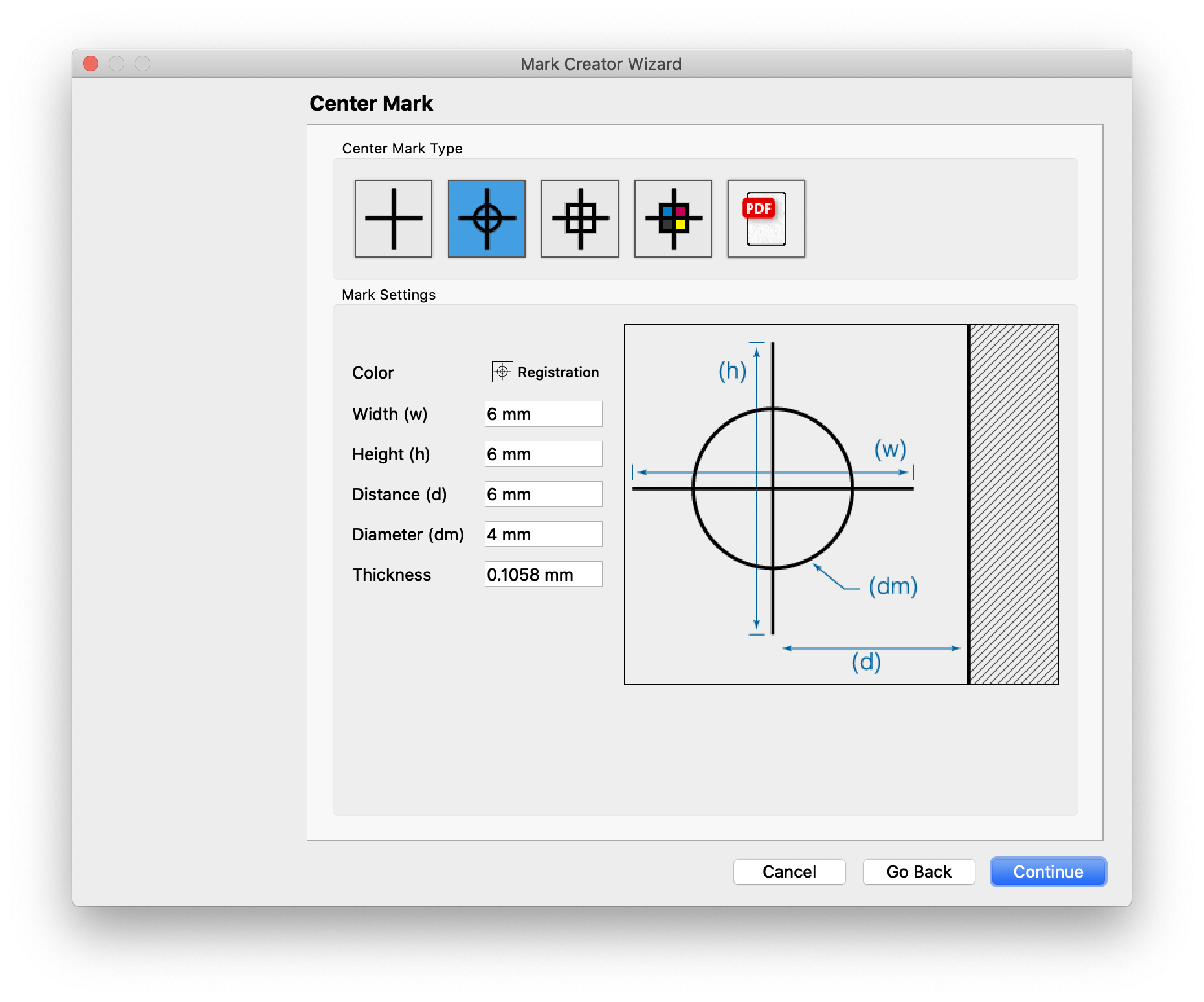
# Center
Center marks place a center registation mark on the layout.
| Field | Description |
|---|---|
| Center Mark Type | Choose from the predefined mark types, or select a custom mark from a PDF |
| Color | Sets the Colorof the mark |
| Dimensions | Set the width and height of the mark, which correspond to the dimensions in the graphic |
| Distance | Sets the offset distance for the mark from the edge of the sheet |
| Diameter | For marks with a circle, defines the diameter of the circle |
| Thickness | Sets the stroke thickness |
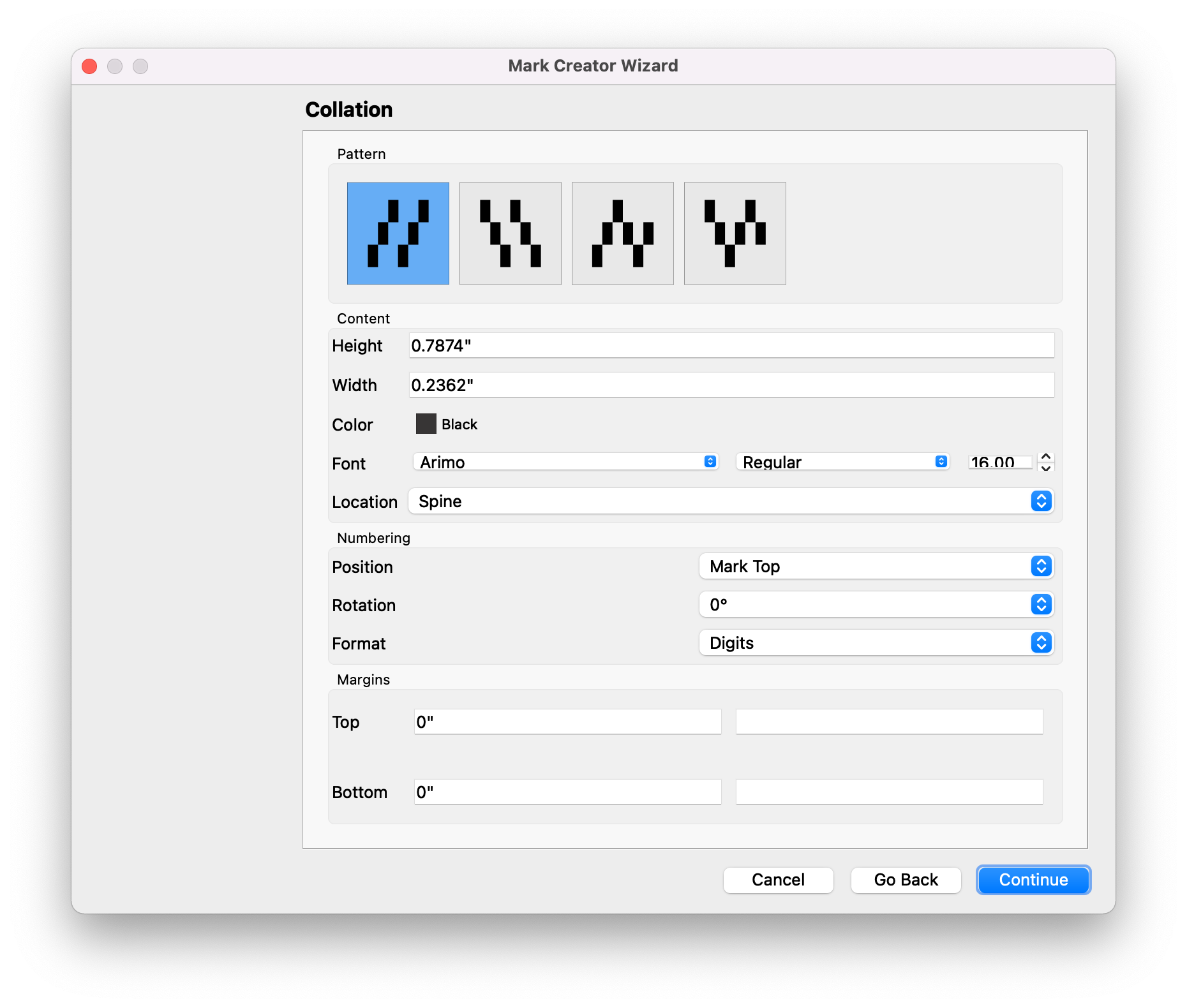
# Collation
Collation marks place a mark for delineating collation patterns across collated signatures in bookwork. Collation marks are highly configurable with options controlling mark dimensions, color, text numbering position, and font. A location settings allows you to place collation marks in the spine, face, jog, and non-jog folded edges to handle perfect bound, section stitch (Smyth sewn), and saddle stitch binding methods. In addition, text can optionally be placed in user-defined top or bottom margins of the folded edges with full dynamic keyword support.
| Field | Description |
|---|---|
| Pattern | Choose the pattern: Zig Zag Up, Zig Zag Down, Snake Up, or Snake Down |
| Size | Set the width and height of the mark |
| Color | Set the color of the collation mark |
| Font | If using numbering, set the font to be used |
| Location | Define where the number should be placed |
| Position | Sets the rotaiton of the numbering |
| Rotation | Sets number rotation |
| Format | Define the format of the numbering |
| Margins | Set top and bottom margins. In addition, optionally add static or dynamic keyword text to be placed in the margin. |
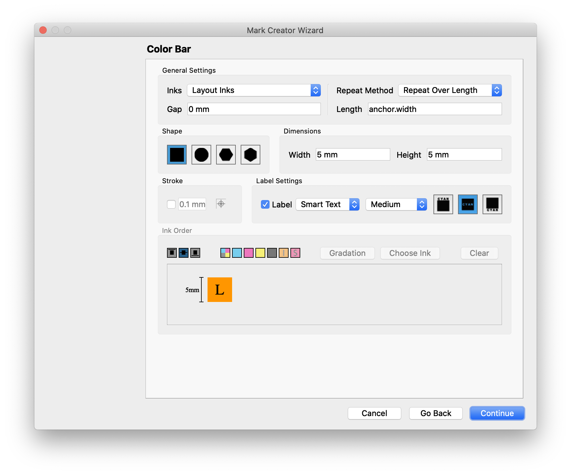
# Color Bar
The Color Bar marks allows you to create a fully customizable Color Bar. To create the bar, first choose the general settings, shape, dimensions, optional stroke, and label. If you want to create a custom bar, choose the "Choose Inks" option in the Inks dropdown of the General Settings. Then, in the Ink Order section, click and drag the ink swatches into the box below to create the Color Bar configuration. The swatches, left to right, are a CMYK shortcut, then cyan, magenta, yellow, black, inks by index, and finally spot inks by index. You can also create custom gradations, as well as choose inks from your ink library.
| Field | Description |
|---|---|
| Inks | Choose Layout Inks, Item Inks, or manually Choose Inks |
| Gap | Sets the gap between ink swatches |
| Repeat Method | Define how the Color Bar should be repeated |
| Length or Number of Repeats | Specifies either a length relative to the anchor item, or the number of times the bar is repeated |
| Shape | Choose the swatch shape |
| Dimensions | Defines the Sizeof the swatch |
| Stroke | Optionally add a stroke, define the thickness, and Color |
| Label | Optionally add a label to each swatch, choose what kind of label, and positioning |
| Ink Order | If using Choose Inks, this lets you set the ink order by dragging and dropping the inks into the box below to create a custom swatch order. You can drag the colors in, and then double click on a swatch to customize it |
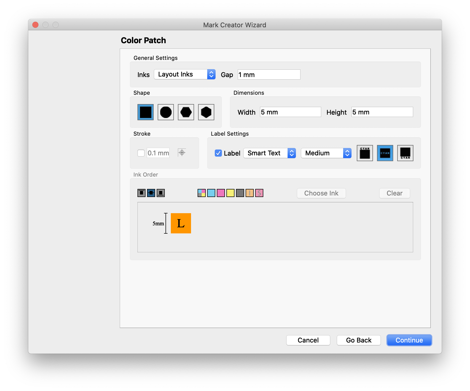
# Color Patch
Color Patch marks are very similar to Color Bars, but do not repeat.
| Field | Description |
|---|---|
| Inks | Choose Layout Inks, Item Inks, or manually Choose Inks |
| Gap | Sets the gap between ink swatches |
| Shape | Choose the swatch shape |
| Dimensions | Defines the Size of the swatch |
| Stroke | Optionally add a stroke, define the thickness, and Color |
| Label | Optionally add a label to each swatch, choose what kind of label, and positioning |
| Ink Order | If using Choose Inks, this lets you set the ink order by dragging and dropping the inks into the box below to create a custom swatch order. You can drag the colors in, and then double click on a swatch to customize it |
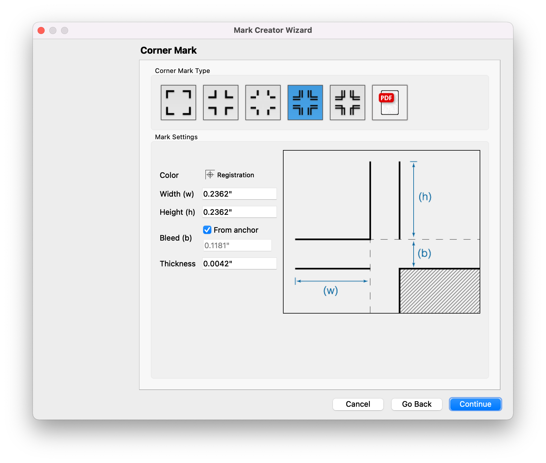
# Corner
Corner marks add marks to the corners of the item they are anchored to, whether plate, sheet, group, or product.
| Field | Description |
|---|---|
| Mark Type | Select the type of corner mark to be used, or upload a PDF to use a custom corner mark |
| Color | Define the Colorof the corner mark |
| Dimensions | Set the dimensions of the mark. The graphic on the right side of the mark creator wizard displays a representation of the mark to easily allow you to correlate what each dimension affects in the mark |
| Bleed | The distance to offset the corner mark to account for any potential bleed. Can use the bleed of the item the mark is anchored to by checking the From anchor button. |
| Thickness | The stroke thickness of the corner mark |
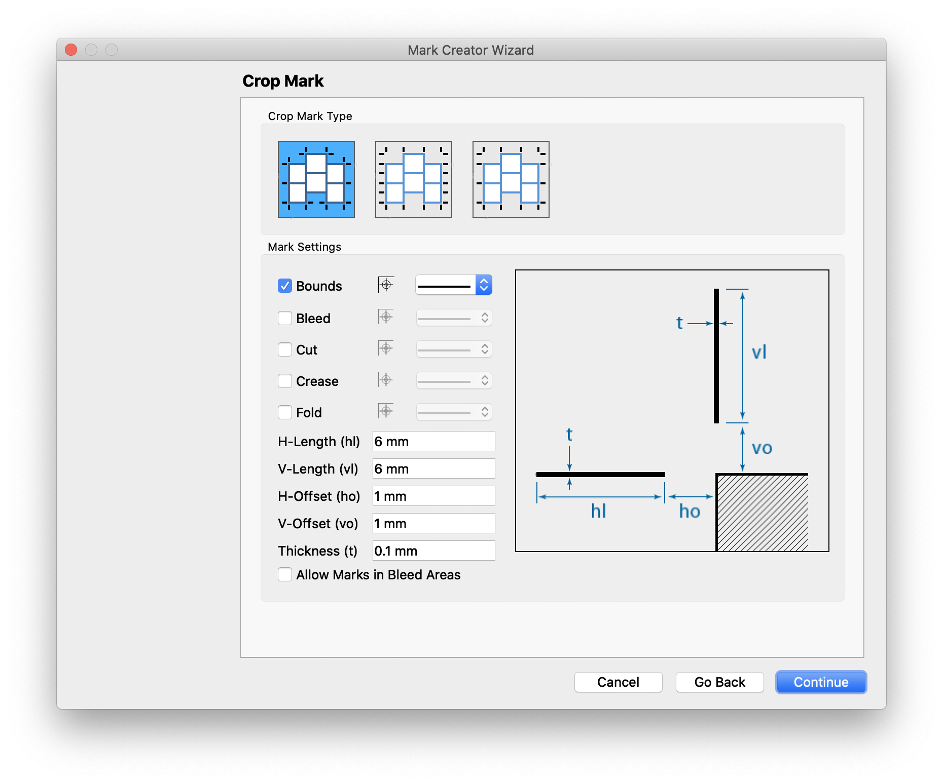
# Crop
Crop marks add tick marks around a sheet or group to easily allow for a cutter to separate items in a group or on a sheet. Crop marks can only be placed with Smart Placement and attached to either a sheet or a group.
| Field | Description |
|---|---|
| Mark Type | Select the type of crop mark to be used. The differences here revolve around where the ticks are placed, either around the bounds of each product, the bounds of a rectangle formed by all the products, or marks for every cut, even for products not on the outside of the group or sheet. |
| Bounds | Select if you want to create a mark for the bounds of the group or sheet, along with the Colorof the crop mark and line style |
| Bleed | Select if you want to create a mark for the bleed of products in the group or sheet, along with the Colorof the crop mark and line style |
| Cut | Select if you want to create a mark for the cut lines of products in the group or sheet, along with the Colorof the crop mark and line style |
| Crease | Select if you want to create a mark for the crease lines of products in the group or sheet, along with the Colorof the crop mark and line style |
| Fold | Select if you want to create a mark for the folds of products in the group or sheet, along with the Colorof the crop mark and line style |
| Length | Specify the length of each tick mark |
| Offset | Specify the offset of each tick mark |
| Thickness | Specify the stroke thickness |
| Allow Marks in Bleed Areas | Optionally allow crop marks to extend into product bleed |
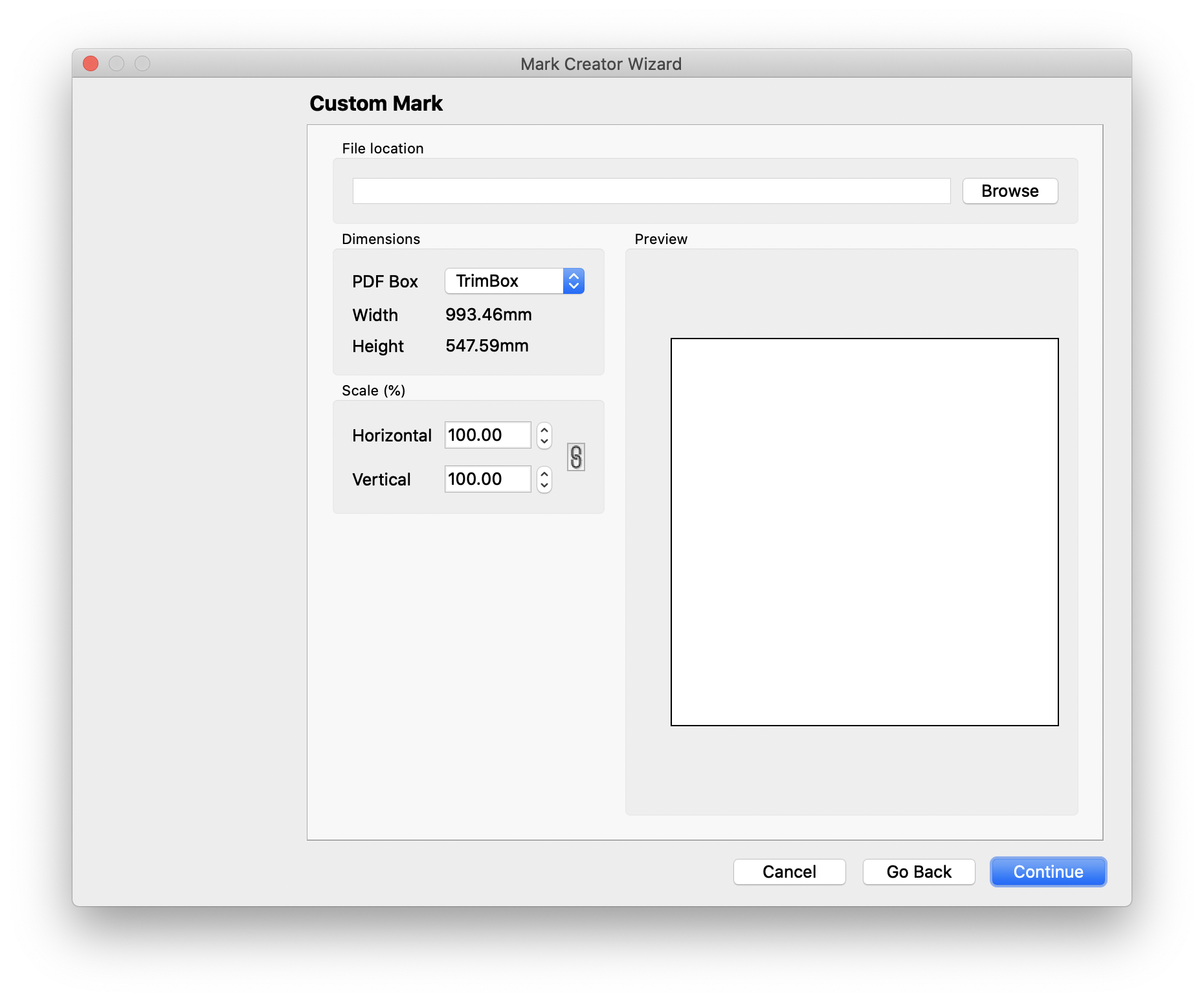
# Custom
Custom marks allow you to create marks from an existing PDF file.
| Field | Description |
|---|---|
| File Location | Choose the where the PDF is located that you want to use for this mark. |
| PDF Box | Select which PDF box to use for the dimensions of the mark. |
| Scale | Optionally scale the mark horizontally or vertically |
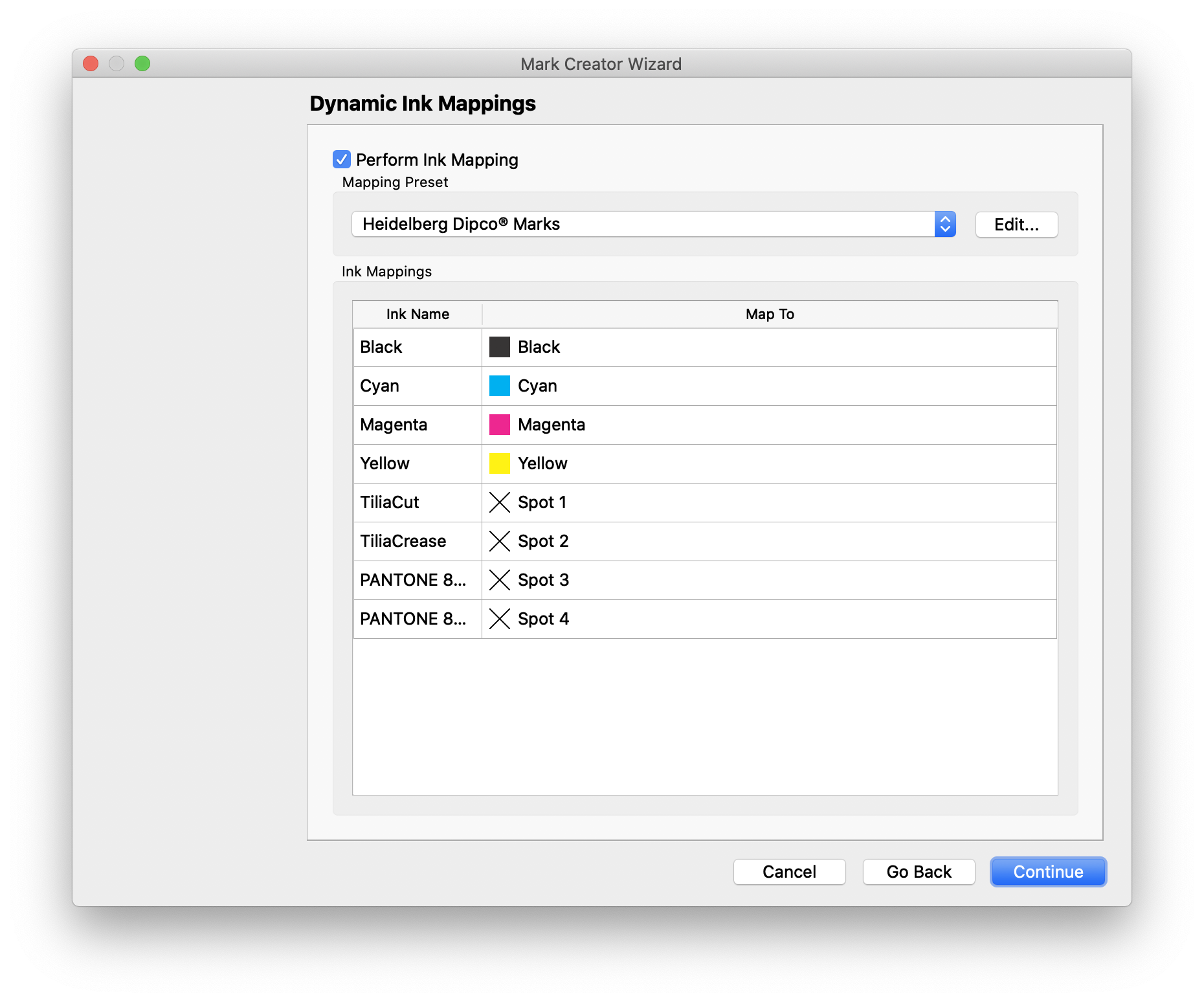
# Custom Mark Ink Mapping
When using a custom mark, Phoenix can dynamically remap inks in the PDF to an ink of your choosing.
| Field | Description |
|---|---|
| Perform Ink Mapping | Choose this option to enable the ink mapping |
| Mapping Preset | Choose a preset, or click edit to create or modify an existing preset |
| Ink Name | Ink Name lists the names of inks in the input PDF to be remapped |
| Map To | Map To lists the corresponding ink that the Ink Name of the input PDF needs to be mapped to |
Note
The Ink Mappings will only appear if the pdf used has an ink name that matches what's in the ink mapping. So, for instance, if the ink mapping is only for the ink "Reflex Blue" but the custom mark pdf doesn't contain "Reflex Blue", the mapping won't appear in the available mappings dropdown.
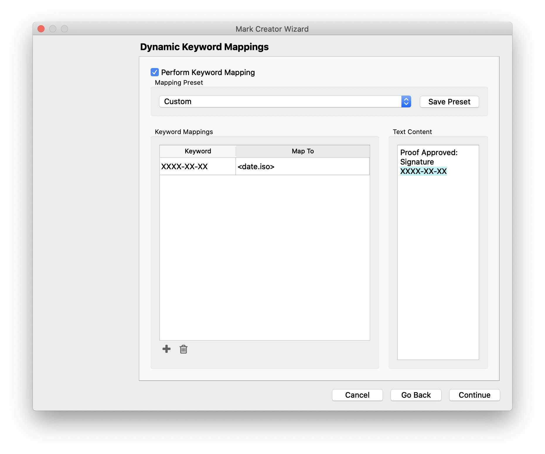
# Custom Mark Keyword Mapping
When using a custom mark that contains text, Phoenix can automatically remap text or parts of text from the input PDF using keywords.
| Field | Description |
|---|---|
| Perform Keyword Mapping | Choose this option to enable the keyword mapping |
| Mapping Preset | Choose a preset, or click edit to create or modify an existing preset |
| Keyword | Define the keyword that appears in the input PDF that needs to be mapped to something else |
| Map To | Choose what the keyword should be remapped to in the mark |
| Text Content | The Text Content field displays the text in the input PDF and highlights any keywords that have been added as a mapping in the Keyword Mappings section |
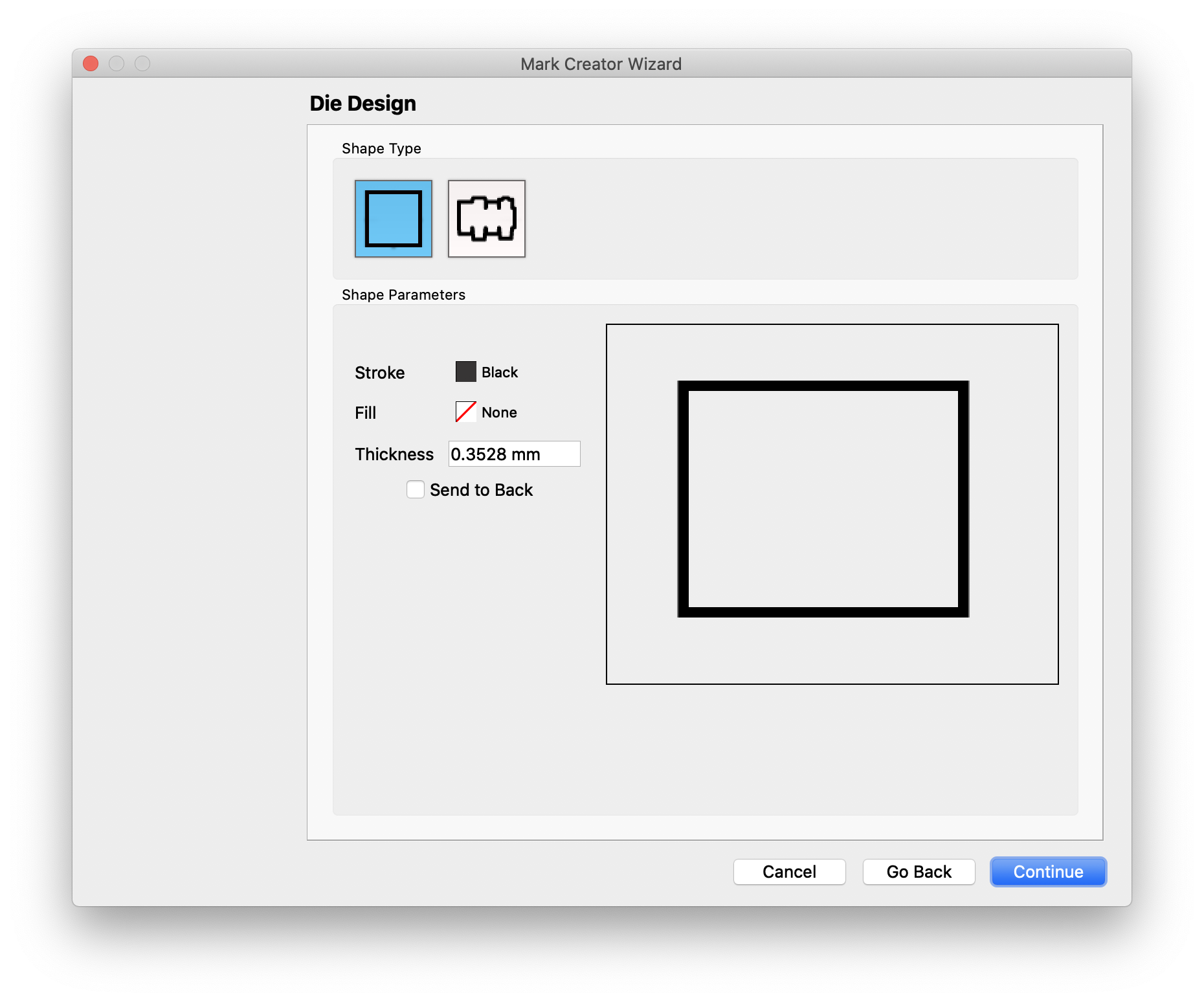
# Die Design
The Die Design mark creates a mark in the shape of the product.
| Field | Description |
|---|---|
| Shape Type | Choose from a rectangular shape or die shape |
| Color | Select the Colorof the shape stroke and fill |
| Thickness | If using a stroke, set the stroke thickness |
| Send to Back | Optionally send the shape behind the product |
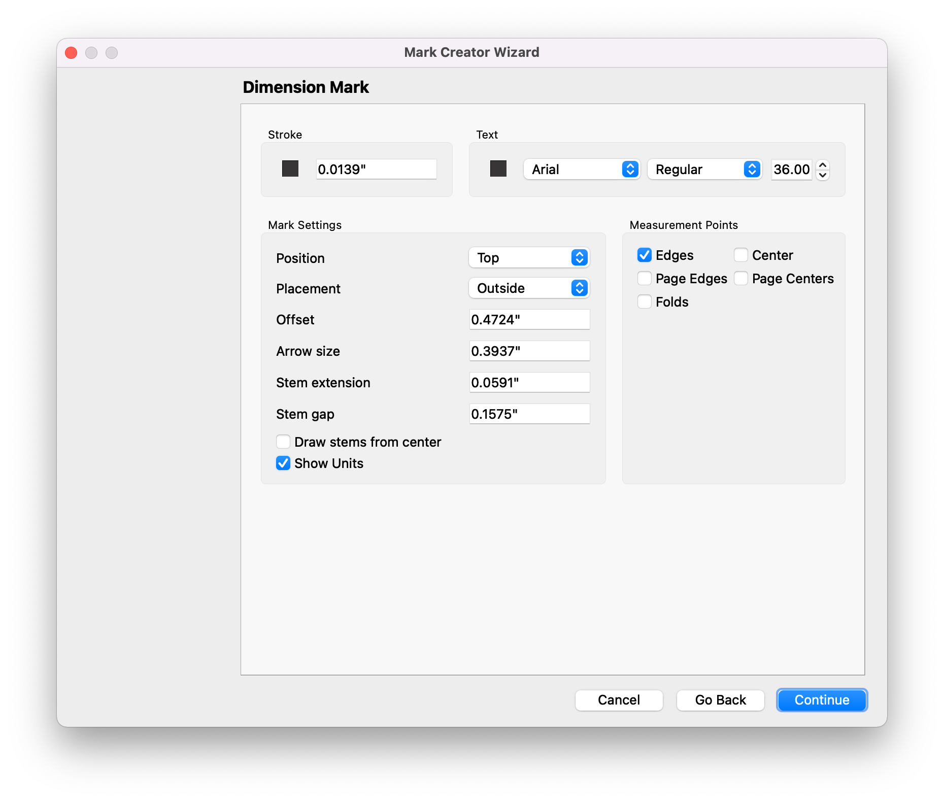
# Dimension
Dimension marks add dimensions to the object they are anchored to. New to v8.0, Dimension marks no include options for folded and bound signatures!
| Field | Description |
|---|---|
| Stroke | Define the stroke Colorand thickness for the dimension lines |
| Text | Choose the dimension text typeface, style, and font Size |
| Position | Choose where you want the mark to go, top, bottom, left, or right |
| Placement | Select whether the value should go outside or inside of the dimension lines |
| Offset | Set the offset distance for the dimension mark |
| Arrow Size | Set the Sizeof the dimension line arrow point |
| Stem extension | Set how far the stem should extend from the product |
| Stem gap | Define the gap Sizebetween the stem and the product |
| Draw stems from center | Optionally choose to draw stems from the center |
| Show Units | Optionally choose to have dimension units displayed in the mark |
| Measurement Points | Set where the dimensions should be based on. Choose the edge or center of the product, or for folded products choose Page Edges, Page Centers, or Folds. |
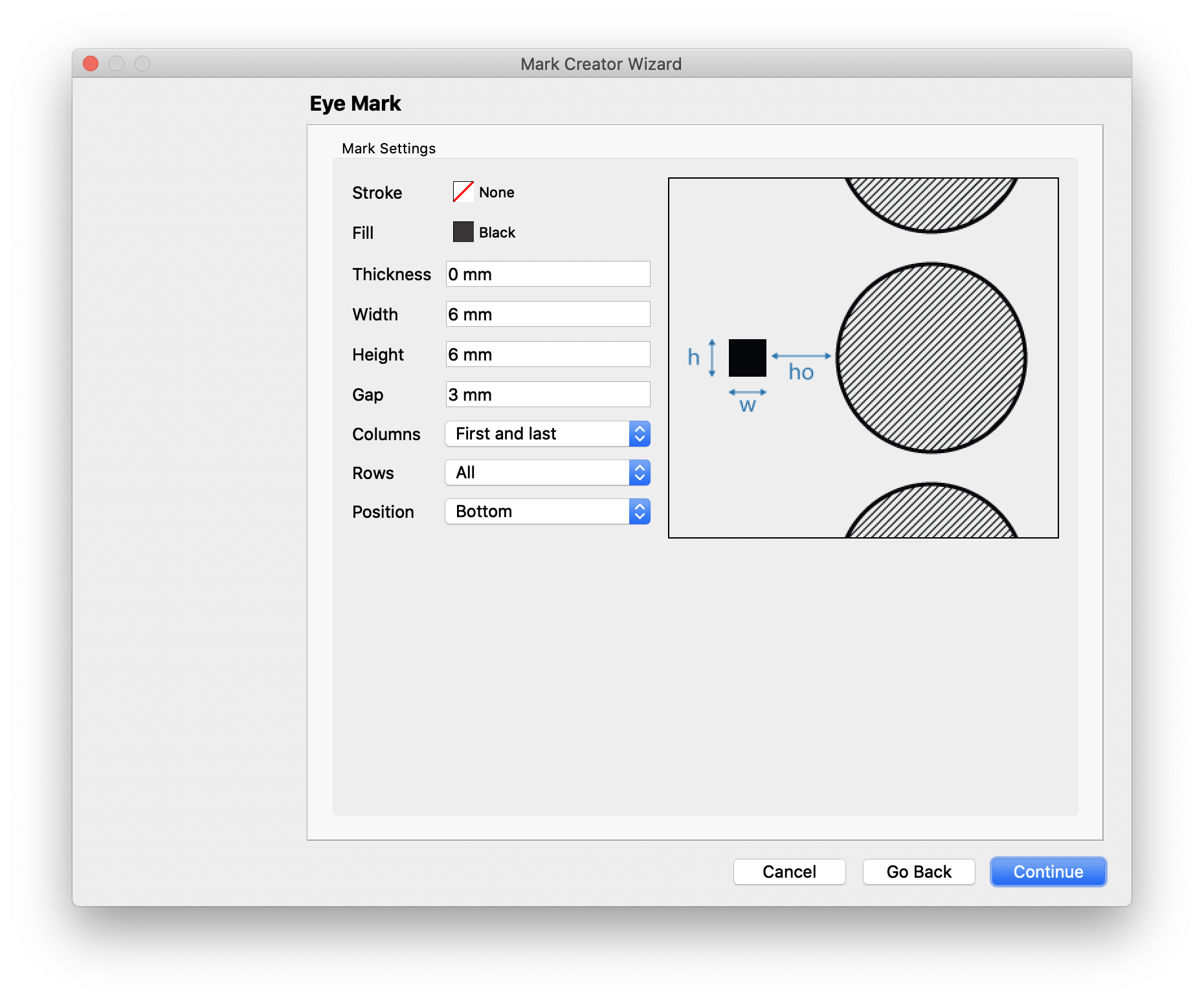
# Eye Mark
Eye marks are rectangular marks typically used in packaging used to indicate the position of each product in a layout to a camera mounted on a finishing device.
| Field | Description |
|---|---|
| Color | Select the Colorof the shape stroke and fill |
| Thickness | If using a stroke, set the stroke thickness |
| Dimensions | Set the dimensions of the mark. The graphic on the right side of the mark creator wizard displays a representation of the mark to easily allow you to correlate what each dimension affects in the mark |
| Gap | Set the distance of the gap between the product and the eye mark |
| Columns | Select which columns the eye mark should appear on |
| Rows | Select which rows the eye mark should appear on |
| Position | Set the position of the eye mark to be at the bottom, center, or top of each product |
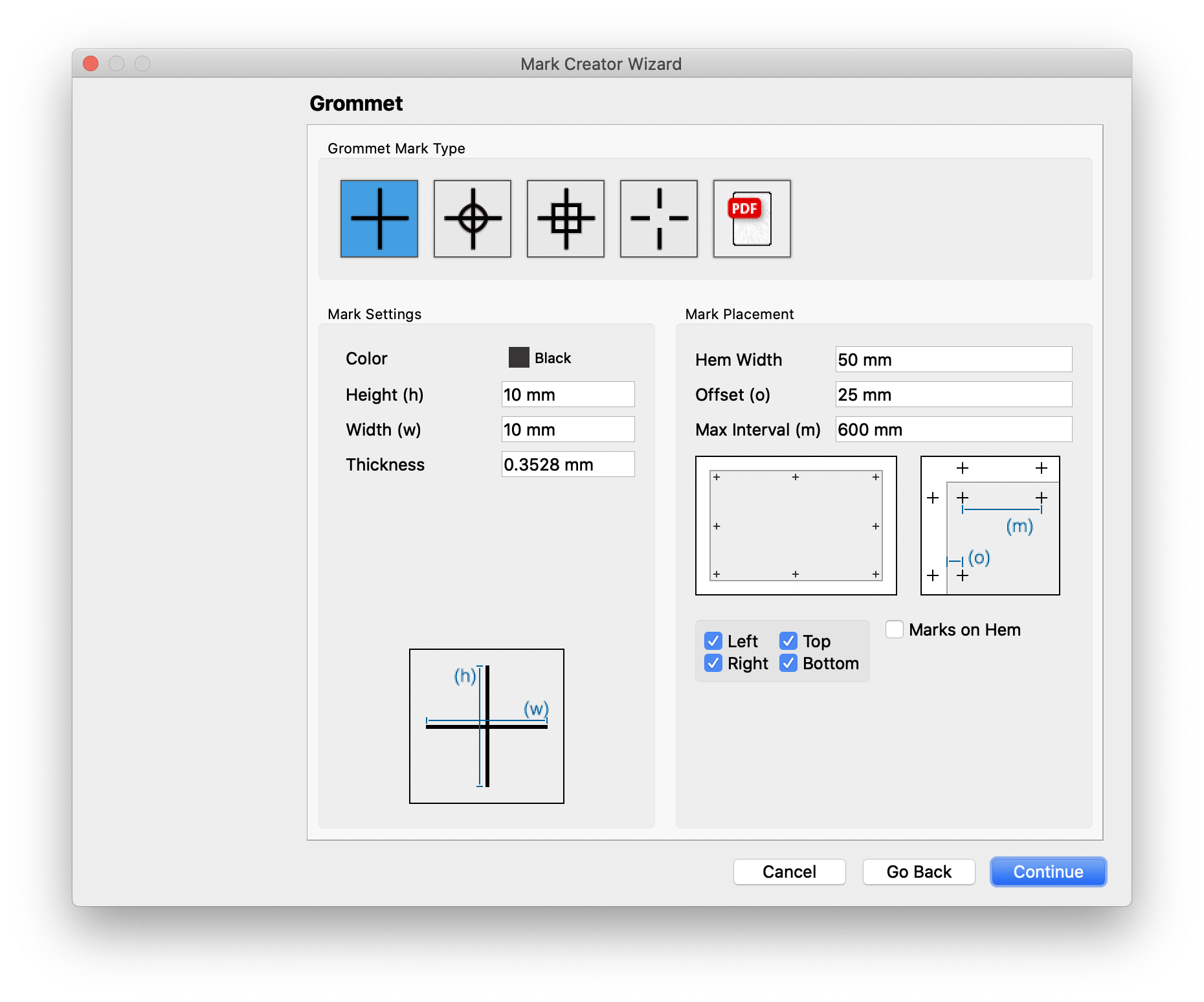
# Grommet
| Field | Description |
|---|---|
| Mark Type | Select the type of grommet mark to be used, or upload a PDF to use a custom grommet mark |
| Color | Select the Colorof the grommet mark |
| Dimensions | Set the dimensions of the mark. The graphic below this setting displays a representation of the mark to easily allow you to correlate what each dimension affects in the mark |
| Thickness | Set the stroke thickness |
| Hem Width | Set the width of the hem |
| Offset | Set the offset of each mark from the edge of the product |
| Max Interval | Set the maximum interval between grommet marks. Phoenix will automatically distribute Grommet marks at the corners and evenly along each edge, up to this maximum distance |
| Location | Optionally choose to remove marks from one or more sides by unchecking the corresponding side |
| Marks on Hem | Optionally place marks inside the product on the hem. |
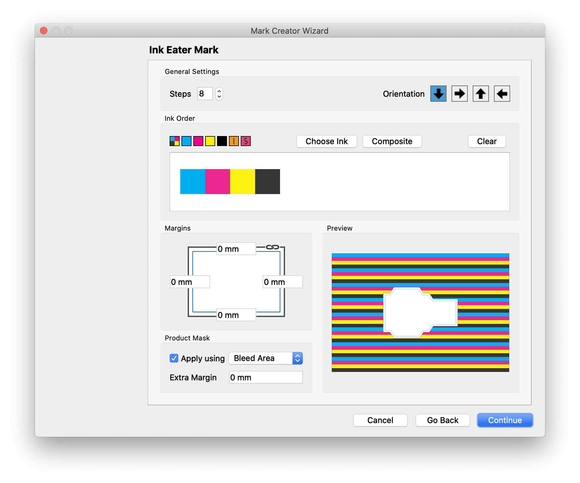
# Ink Eater
Ink Eater marks are used in offset printing to place additional ink in what would otherwise be a non-printing area in order to help ensure consistent ink consumption across the plate.
| Field | Description |
|---|---|
| Steps | Defines the number of repeats of the ink order specified below |
| Orientation | Sets the direction that the ink eaters appear, vertically or horizontally, as well as the order the ink order appears |
| Ink Order | The ink order defines how the inks appear. You can add inks by clicking and dragging from the swatches into the box below, or click either the Choose Ink or Composite button. You can also click and drag to rearrange swatches, or double click on a swatch to edit it. |
| Margins | Define the margin around the sheet where ink eaters should not appear |
| Apply using | Choose to mask out the product, and which product area to use |
| Extra Margin | Give an extra margin around the product where ink eaters should not appear |
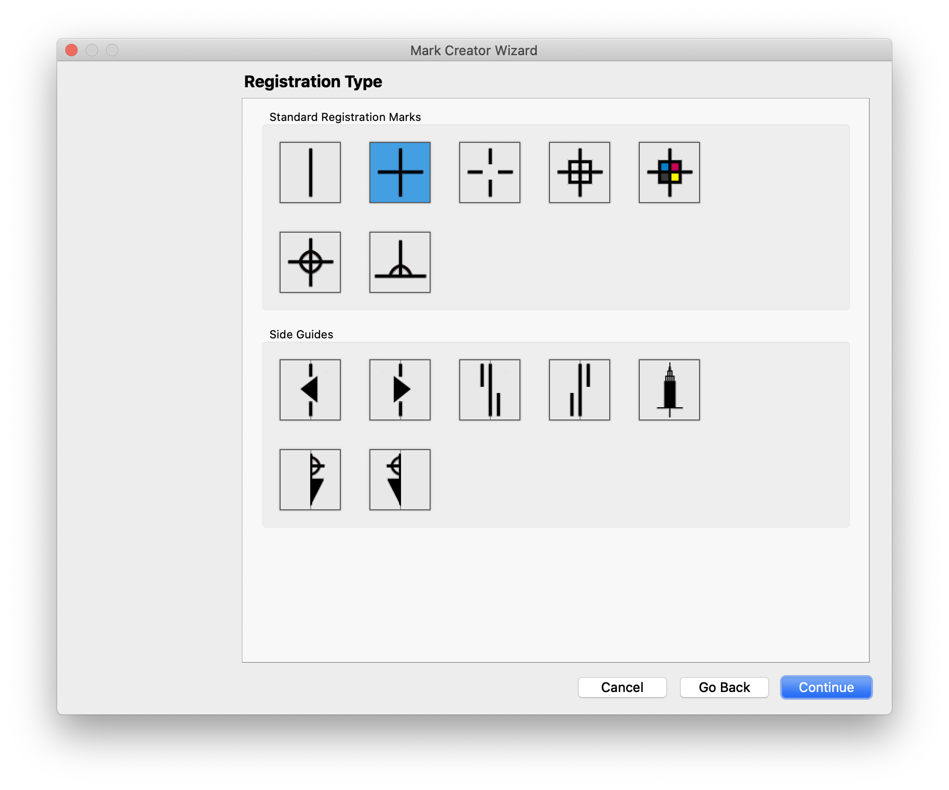
# Registration
Registration marks are used to ensure the print inks are in register. This includes registration marks as well as side guides.
| Field | Description |
|---|---|
| Standard Registration Marks | Select the style of registration mark to use |
| Side Guides | Select the style of side guide to use |
The next page in the wizard displays the sizing for the registration mark
| Field | Description |
|---|---|
| Dimensions | Set the dimensions of the mark. The graphic on the right side of the mark creator wizard displays a representation of the mark to easily allow you to correlate what each dimension affects in the mark |
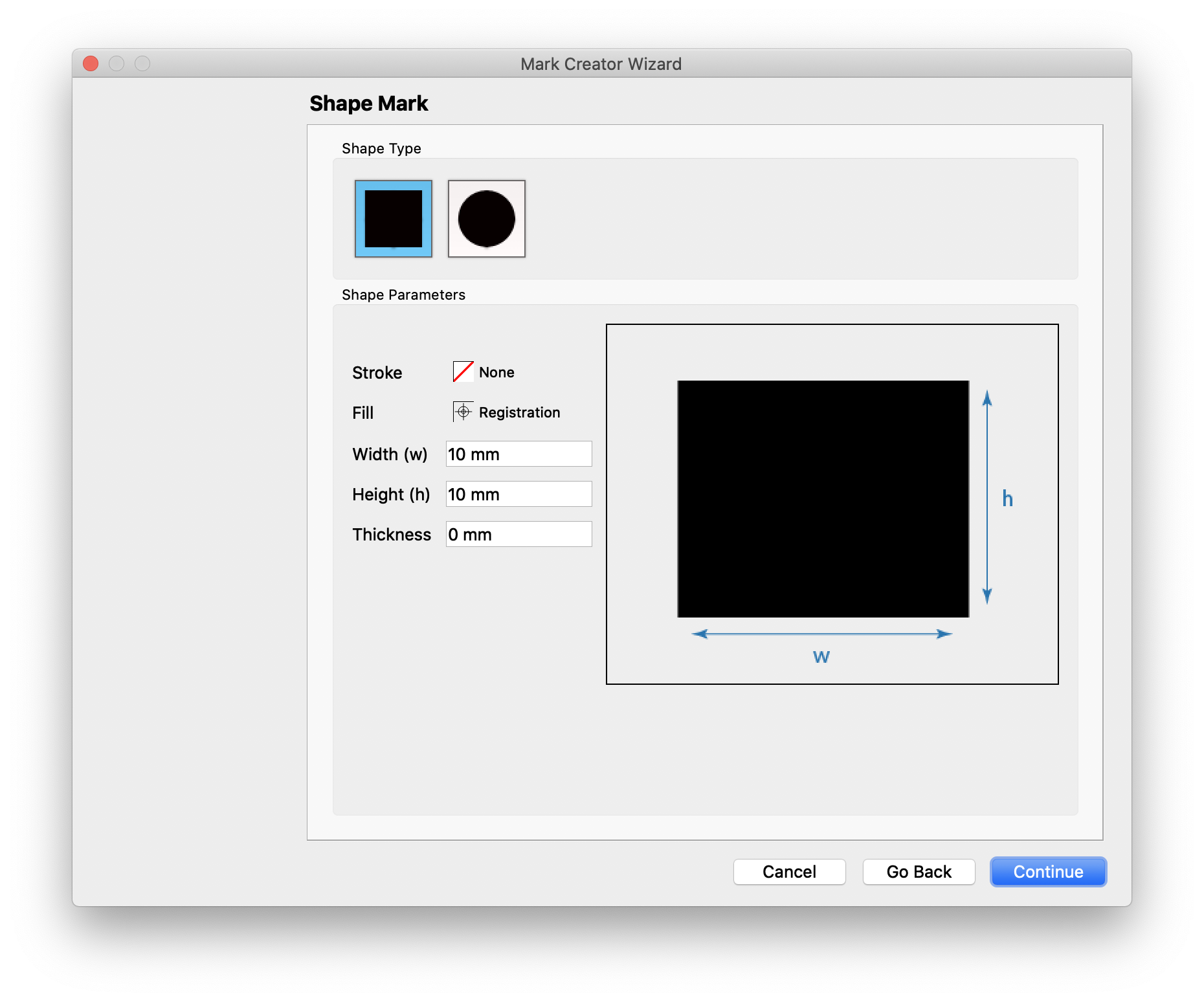
# Shape
| Field | Description |
|---|---|
| Shape Type | Choose between a rectangle or ellipse shape mark |
| Color | Select the Colorof the shape stroke and fill |
| Dimensions | Set the dimensions of the mark. The graphic on the right side of the mark creator wizard displays a representation of the mark to easily allow you to correlate what each dimension affects in the mark |
| Thickness | If using a stroke, set the stroke thickness |
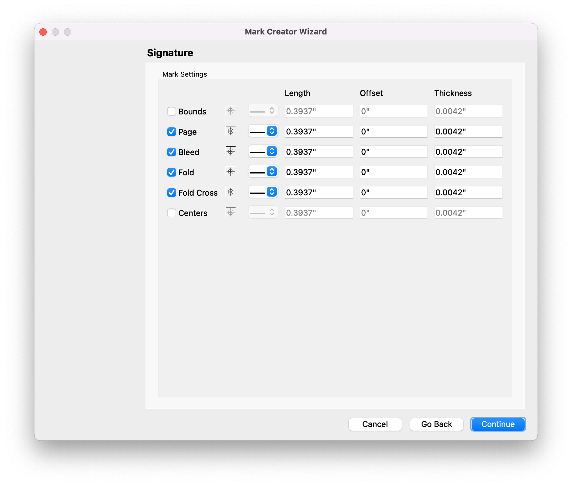
# Signature
Signature marks have been added for folded and bound signatures with options delimiting signature bounds, page edges, page centers, bleeds, folds, and fold crosses. Line color, length, offset, and thickness can be customized for each delimiter type.
# Text
Text marks allow you to add static and dynamic text to a layout.
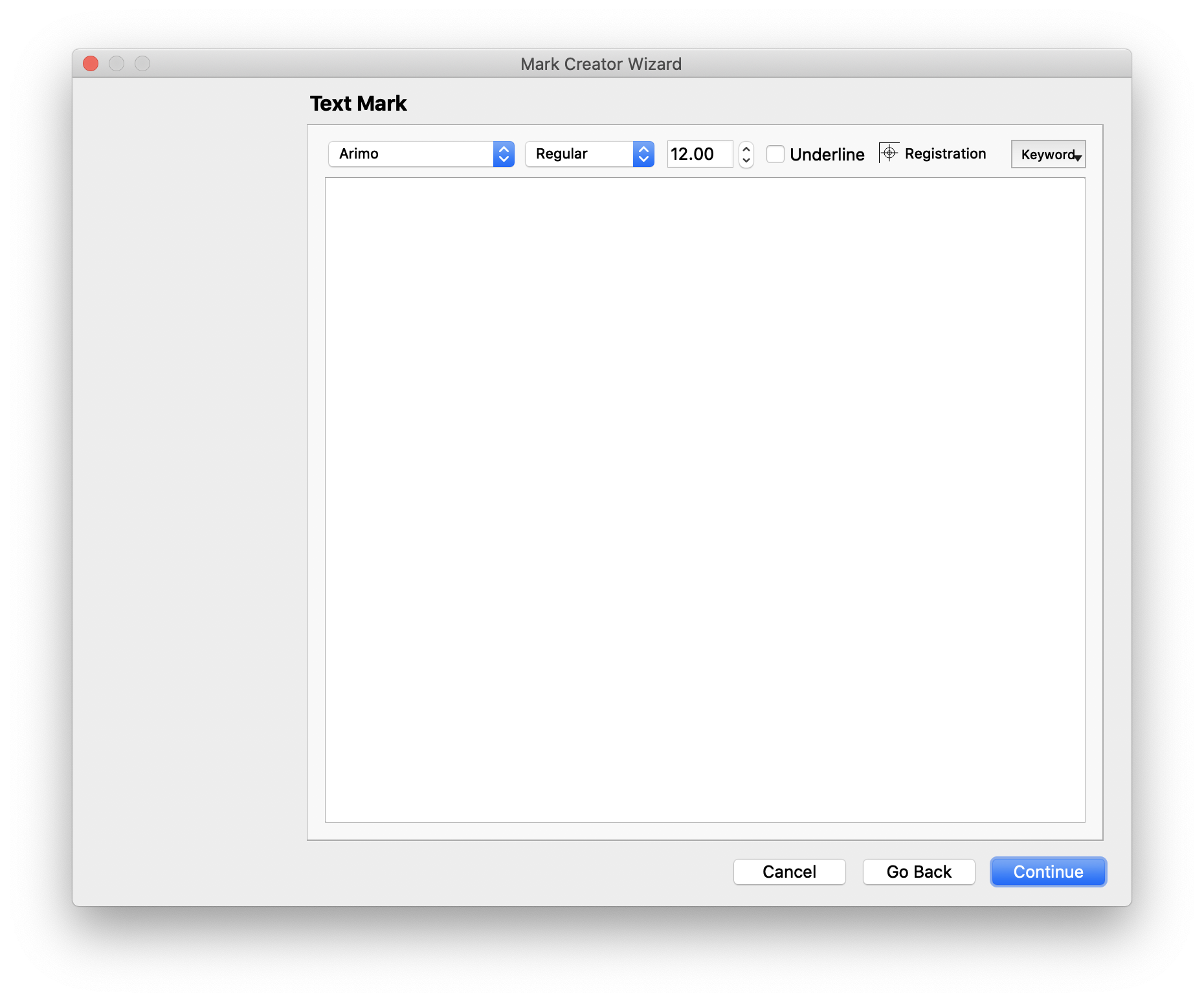
| Field | Description |
|---|---|
| Font | Choose the typeface, style, and font Size |
| Underline | Optionally add an underline to the text |
| Color | Select the Colorof the text |
| Keywords | Add dynamic keywords to the text content |
| Text Box | Add the text to be used in the mark here |
Note
Dynamic keywords will only appear if attached to the relevant item. For example, if the mark is using manual placement, product keywords are not available. If the text mark is anchored to a product, however, product keywords are available in the dropdown.
# Script
The optional Scripting module allows you to create custom marks using javascript, which open up the full power of Phoenix's drawing tools to allow you to create any mark you can think of. The settings are fairly straightforward, since the mark itself is completely driven from the script. The main section of the window is where you can write your script. You can also load a script from a library or load one from an external file.
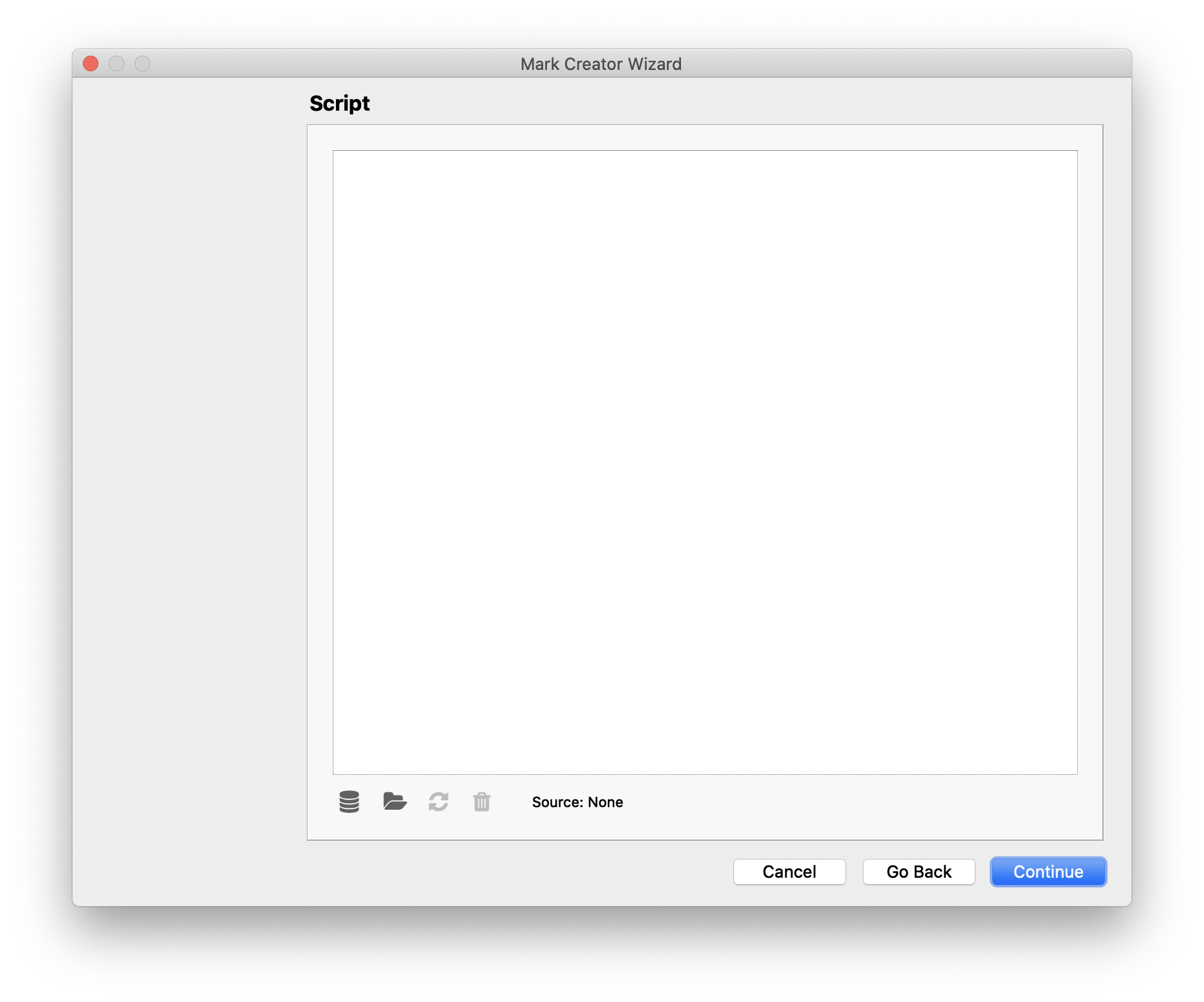
| Field | Description |
|---|---|
| Select from library | Choose a saved script from your library |
| Load from file | Load a script in from a .js file on your disk |
| Reload from source | Updates a mark that has previously been loaded from disk and has since been modified. |
| Clear | Removes any mark currently loaded |
# Assigning Product Group Marks Shortcut
By default, dropping a Group or Product Mark from the Marks Panel into Layout View will apply that mark to all Group or Products in the current side of the layout respectively. You can assign a Group or Product Mark to a specific Repeat item or specific Product by holding down the Control key.
Dropping Group or Product Marks into Layout View applies that mark globally to the project. This means that mark will be in all current and future Groups/Products unless removed or hidden explicitly within them. By using the Control key shortcut you can apply the smart mark to the specific Repeat the cursor is under when releasing the mouse button in the case of Group Smart Marks or, in the case of Product Smart Marks, you can apply the mark to the product that a product item belongs too under the cursor. The mark will appear only in instances of the given product in the project.
# Assigning Product Mark to Single Product Item Shortcut
You can assign a Product Mark to one specific instance of a Product in a given layout by holding the Alt key while dropping the mark into Layout View.
When the Alt key is held down while dropping a smart Product Mark into the Artboard it will apply the mark only to the product item under the cursor. The mark will not be visible in other product items belonging to the same product and is not applied to other products in the project.
This shortcut works by applying the mark to the product but turning on visibility of the mark only in the single product item in the Artboard. This means you can turn visibility of that mark on in other product items at any time. Note: Non-visible items are not included at export time.
This shortcut differs from the Assigning Product/Group Marks Shortcut where the mark becomes visible across all product items in the project, not just the single item under cursor.
# Mark Inspection Mode
To highlight all the marks in Layout View, navigate to the Tools menu and select Mark Inspection, or use the keyboard shortcut Control + Shift + M. Mark Inpsection Modeprovides a clear way to verify mark placement.
You can adjust the visibility of the Products in the Layout as well as the Marks by adjusting the sliders in the Mark Inpsection toolbar at the top of the window. You can also change the highlight Colorof the Marks by clicking the swatch next to the "Marks" text in the Mark Inspection toolbar.
← Templates Marks 2.0 🆕 →